World record-breaking bridge
Engineering principles of bridges
🌉 Simple cantilever, suspension, and cable-stayed bridges and their history
Simple cantilever bridges, which project horizontally into space and are supported at only one end, are as old as civilisation, but in the late 19th century, engineers began to explore the potential for combining the cantilever principle with steel trusses to span much larger distances, notably on the Forth Bridge.
A suspension bridge has suspension cables hung from two or more towers that are held by massive anchorages at the ends. The cables support hangers, which in turn support the deck. Origins may be traced back to ancient rope bridges, but the modern suspension bridge emerged with the application of iron to provide a robust long-span bridge, such as Thomas Telford’s 176-metre-span Menai Bridge in 1826. Wire cable replaced chain links, which led to a series of great US suspension bridges, most famously the 1937 Golden Gate Bridge with its 1,280-metre main span.The Forth Road Bridge marked the start of British dominance of suspension bridge design, including the 1981 Humber Bridge with its (then) world’s longest span of 1,410 metres. Later, Japanese engineers took the lead: the 1998 Akashi Kaikyo Bridge still has the world’s longest span at 1,991 metres. Suspension bridges remain the form of choice for the very longest spans.
A cable-stayed bridge has one or more towers from which cables support the deck, in either in a fan-like pattern or a series of parallel lines. They have been in development since the 16th century and usedwidely since the 19th century, sometimes in conjunction with suspension cables, such as New York’s Brooklyn Bridge or London’s Albert Bridge. They fell out of favour in the 20th century, but enjoyed aresurgence from the 1950s as new materials and equipment and more sophisticated analytical techniques lowered their relative price – notably for rebuilding large bridges in Germany under pioneers such as the structural engineer Fritz Leonardt. They have become established as the form of choice for a wide range of long spans.
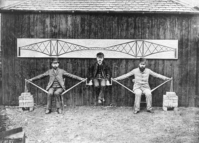
Benjamin Baker staged this ‘human cantilever’ photograph with three of his engineers in 1887. The photograph neatly illustrates the structural principles of his Forth Bridge. The short central suspended span, which isholding up engineer Kaichi Watanabe in the centre, is supported by two of the huge cantilever towers: the compression members are represented by wooden poles and the tension members by the men’s outstretched arms, while the bricks represent the use of the end piers as anchors to provide stability © courtesy of the Institution of Civil Engineers
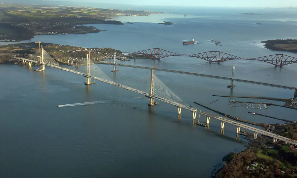
The Forth Road Bridge has been successfully carrying road traffic across the Forth estuary since 1964, but with loads now weighing many times more than what it was designed for and concerns that cable corrosion would force premature closure, a replacement became an urgent necessity. Although many options were considered, the choice was straightforward in the end. A modern cable-stayed bridge was far cheaper and quicker to build than a tunnel or a suspension bridge, and a location close to the existing bridge made connections into the existing road network far easier. The clincher was Beamer Rock, a natural outcrop in the middle of the Forth that provided the ideal location for the central tower of a three-towered cable stayed bridge.
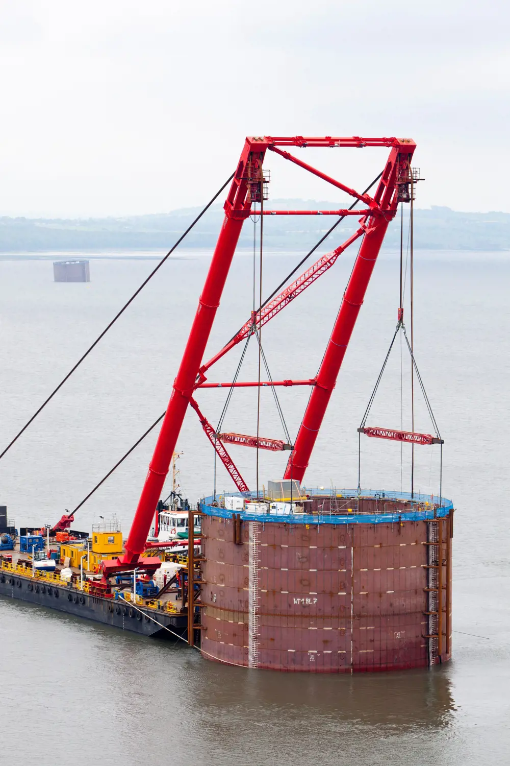
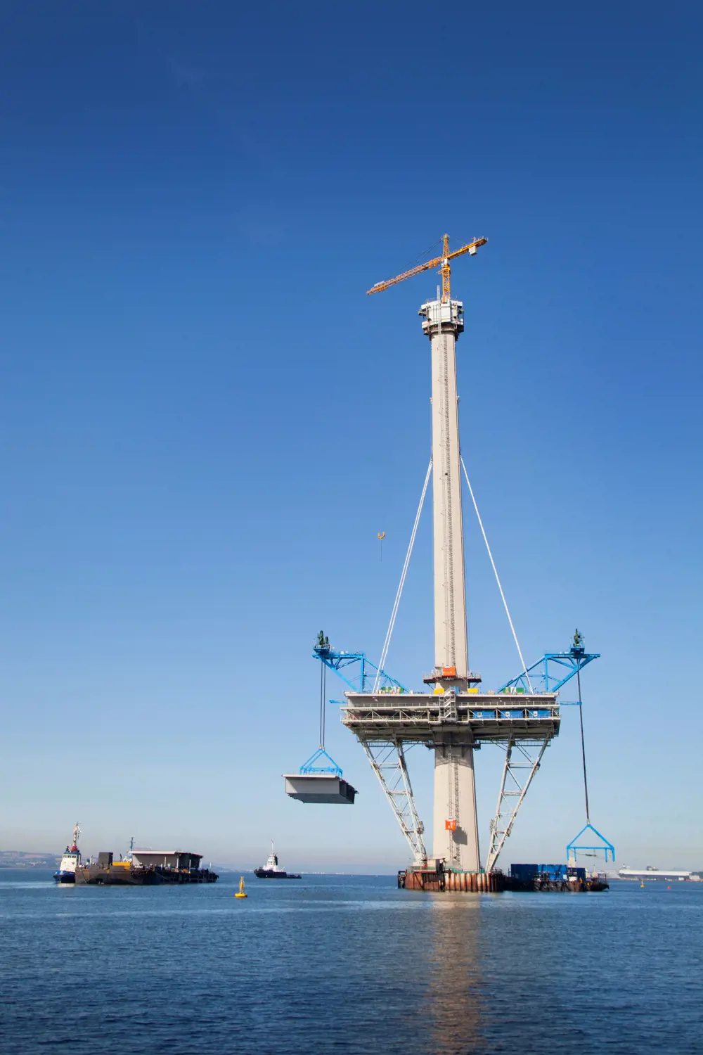
A cylindrical caisson for the tower foundations is floated out by barge and lowered into place on the seabed by shear-leg crane © Transport Scotland
Modern design
The design for the new bridge was initially developed by Transport Scotland’s (TS) consulting engineers Jacobs Arup, led by Arup’s global bridge design practice leader Naeem Hussain (who was awarded the Royal Academy of Engineering’s Prince Philip Medal in 2012 for his groundbreaking work on bridges, including Queensferry). The final design was developed in a joint venture between Ramboll, Sweco, and Leonhardt, Andrä und Partner, while construction was the responsibility of Forth Crossing Bridge Constructors (FCBC).
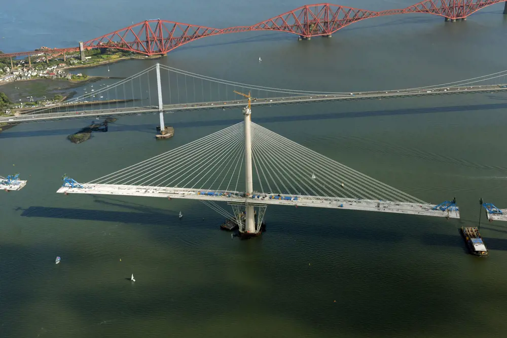
The bridge’s form sits in harmony with its two well-known neighbours, each representing the pinnacle of bridge engineering of its generation. The design’s most distinctive – and unusual – feature is the crossover of the cables at the middle of each span. This stems from a peculiarity of three-masted cable-stayed bridges: as the central tower is not connected to a stiff back-span structure (which would reduce any twisting), an out-of-balance live load on just one of the main spans can cause large deflections in the central tower and deck, and large bending movements in the tower. This can be countered, for example, by making the central tower larger and stiffer, making the deck much deeper and stiffer, or by tying the tower tops together with additional cables. A much more elegant, and economical, alternative was to design the stay cables to overlap over almost a quarter of each 650-metre-long main span, which effectively adds greatly to the stiffness of the deck without increasing its size. This has never been done before on a large bridge.
The design’s most distinctive – and unusual – feature is the crossover of the cables at the middle of each span
This design formed the basis of consultation and planning, and the subsequent Bill received Royal Assent in January 2011. Meanwhile, bids were invited to do both the detailed design for the bridge and its approaches, and the construction. Tenderers were given a set of ‘definition drawings’ that indicated the requirements for the overall form and geometry of the bridge, including the shape of the ‘mono-towers’ and the arrangement of the cables in two lines down the centre of the bridge, together with a ‘specimen design’ that gave an example of how all other aspects could be designed. In early 2011, the contract was awarded to FCBC and its designers for £790 million, for completion by the middle of 2017.
FCBC’s early decisions included opting for a composite design for the trapezoidal box sections of deck for the bridge and approaches (steel with a concrete top, rather than all steel or all concrete); ordering all major steel components from overseas fabricators in China and Poland. Perhaps most surprisingly – and successful – the engineers chose to service the site and its remote locations in the sea by investing in a 30-strong fleet of floating plant, rather than (as expected) building causeways for road access from the shore. This approach saved both time and cost.
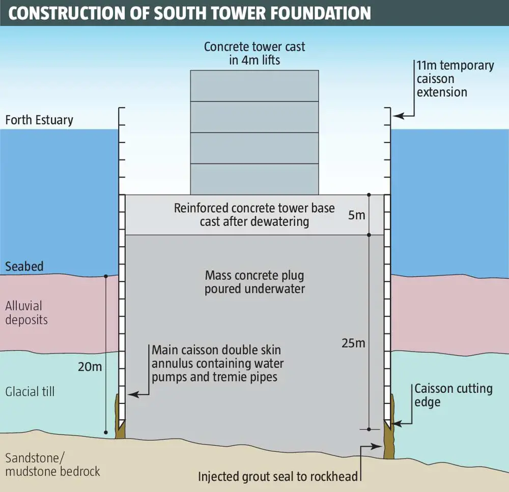
The bridge’s tower foundations were built within huge double-skinned steel caissons. A four-metre-high section of concrete was poured in, before the mould was lifted and re-fixed for the next section to be poured – a process that took up to two weeks © Transport Scotland
Working underwater
The first onsite task was to create the foundations, particularly for the three main towers. As with the bridge’s earlier neighbours, the foundations presented an even greater challenge than the more visible superstructure, and represented around 30% of the total cost. The central tower on Beamer Rock was relatively easy to construct, but the other two had to be sunk through deep water and soft ground to rest on the solid rock beneath. For these, FCBC chose some of the largest steel caissons (large cylinders that were lowered onto the seabed and had thousands of cubic metres of concrete poured into them, which the tower foundations could be laid on top of) ever used in bridge construction.
The largest, for the south tower, was 30 metres tall and 32 metres in diameter, double-skinned with a 400-cubic-metre volume annulus (a ring-shaped structure) between (capped with temporary steel plate so that the air inside provided buoyancy while towing and placing), and a cutting edge at the bottom. This was then carried out into the estuary on a semi-submersible barge, which was partially sunk beneath the caisson, hooked up to a large shear-leg crane. It was then towed into position where it had to be located with 200 millimetres accuracy; a feat that was not easy in a fast-flowing tidal estuary, even with the help of GPS. By slowly releasing air from the annulus, the caisson was gently lowered to the seabed. Concrete was added in the annulus so that it would sink until it was embedded firmly in the soft sediment deposit below. A separate 11-metre-tall single-skin cylindrical steel caisson was then bolted on top so that it would extend above water level as the caisson was sunk further.
As with the bridge’s earlier neighbours, the foundations presented an even greater challenge than the more visible superstructure, and represented around 30% of the total cost
As the concrete tower continues skywards in four-metre ‘jump lifts’, the first deck sections are placed on massive steel falsework round the tower base, and traveller cranes lift new sections into place either side, with the first stay cables already installed © Transport Scotland
The sinking stopped when a corner of the cylinder reached the sandstone bedrock. The perimeter of the caisson was sealed into the rock by a ring of interlocking jet-grouted piles and the remaining soft material was dredged out to expose the bare rock beneath. But then came the most difficult and time-consuming bit of all: vacuum cleaning and minutely inspecting the rock head (in deep, murky water with little visibility) to ensure it was clean and free of large cracks.
Once this was done, the bridge’s foundations could be created on top of the rock head by pouring tremie (underwater) concrete to fill the inside of the caisson. For the south tower foundation, this was a continuous pour of 16,900 cubic metres of concrete over two weeks, supplied by a fleet of barges that worked around the clock from the quayside batching plant. (This was a world record for an underwater marine concrete pour.)
This brought the foundation up to around 15 metres below water level. The remaining water was pumped out and a five-metre-thick reinforced concrete tower base was built on top. Once this was completed, construction of the towers could commence. The hollow, elliptical, tapering heavily-reinforced concrete towers were formed in ‘jump lifts’: a four-metre-high section would be poured using concrete ferried by barge from the shore and pumped in. The moulds were then lifted and re-fixed ready for the next pour. Each lift took about seven to 14 days.
Deck assembly
Meanwhile, all 122 steel troughs for the deck were taking shape in a Shanghai fabrication yard, overseen by a team of engineers from TS and FCBC. Each 250-tonne trough was match-fitted to its neighbour in the factory before being disconnected and transported to Rosyth Docks. Once it reached the docks, reinforced concrete deck up to 460 millimetres thick was added, increasing the weight to around 700 tonnes, before each 4.5-metre deep and 40-metre wide box-section unit could be barged to site.
One of the most awkward tasks was placing the first sections of deck, once the towers had risen above deck level. First, a giant 1,200-tonne-capacity floating shear-leg crane was used to erect a huge temporary structure around each of the tower bases. The structure consisted of two 146-tonne raking triangular trusses (supports) topped by temporary steel platforms. The crane raised the first deck sections and lowered them on to the platforms round the towers and then lifted a traveller crane on to either end.
In October 2016, the central tower and the deck either side were recognised by Guinness World Records as the longest free-standing balanced cantilever in the world. Shortly afterwards, the gaps at the ends were closed and the cantilevers were no longer free-standing © Transport Scotland
Each section of deck was floated out from Rosyth on a barge, lifted up by the traveller crane on a rising tide, placed with precisely the right level and inclination (computer controlled to within two millimetres), and bolted into position. As the tower rose and the deck moved outwards, the first of the 288 cables were installed and tensioned. Each cable consists of up to 109 seven-wire strands encased in a white polyethylene weatherproof sheath up to 315 millimetre dia. The first strand was lifted with the sheath and stressed to 10 tonnes by jacking crews on the towers. The other strands were then pulled through the sheath and stressed one by one. Although stressing could be done within the towers, positioning the cables and threading the strands at the tower tops was done by workers in open baskets hoisting themselves on wire supports up the outside face of each tower, one of the most weather-sensitive operations of the whole project. Eventually, just before the decks met at mid-spans, the central tower and the deck on either side were recognised by Guinness World Records as the longest free-standing balanced cantilever in the world.
the central tower and the deck on either side were recognised by Guinness World Records as the longest free-standing balanced cantilever in the world
The crossing’s most dramatic moment was the closure of the mid-spans. Vertical differences between the two adjacent cantilevers could be as much as four metres before final balancing, which was achieved by a combination of repeated tweaking of the stresses in the cables and the less sophisticated process of shifting the location of plant and ballast on the decks to alter the balance. Using jacks, one side of the deck was ‘pushed’ landwards by 300 millimetres to make space for the final deck section to be lifted in place and fixed on one side, while several hundred measurements were coordinated by computer software that monitored real-time loadings, stresses, orientation and global positioning. Work was suspended if wind speeds reached over six metres a second. Releasing the jacks closed the gap to just five millimetres, and the join was completed by bolting, welding and a concrete ‘stitch’ at deck level. The crossover cables were then added, with a complex sequence of stress readjustment on nearby main cables.
Weather impact
The team had known from the start that weather – particularly high winds – would play a major part in the programme: for example, a deck lift required a four-hour weather window with wind speeds less than 14 metres a second, and less than 11 metres a second for positioning and stressing the cables at the tower tops. However, it was felt that good and bad periods would even themselves out, which proved correct for the first few years.
Caisson sinking was delayed by bad weather, and there were further delays in grouting the seals beneath the caissons and cleaning the rock head. Acceleration measures were introduced, notably increasing the number of traveller cranes from four to six so that deck erection around each tower could operate in parallel rather than in sequence. However, erecting the falsework structures around the towers was much quicker than expected, thanks to benign weather in autumn 2014. Up to the end of 2015, total downtime due to weather was around 25%, close to original expectations, and an early opening date at the end of 2016 was being confidently predicted.
tower construction and cable anchoring were delayed by unrelenting high winds
In 2016, at a time when wind-sensitive operations were at their peak, tower construction and cable anchoring were delayed by unrelenting high winds. Deck erection and the dismantling of temporary works were also affected, and weather-related downtime in 2016 was 40%. The winter of 2016–17 was particularly frustrating: mild, but with periods of exceptionally high winds, which meant that 20 days were lost to wind in February and 16 days in March. The removal of the first tower crane, normally a two-week job, took 65 days. The opening date for the crossing was put back, which created an unfortunate impression of delays. However, completion is now scheduled to be only 10 weeks beyond the date agreed some six years earlier.
Fourth bridge
🚧 The design and fabrication challenges of one of the most recognisable structures in the world
A symbol of Scotland and one of the wonders of the late 19th century, the three-tower four-span Forth Bridge, with its distinctive cantilever-and-beam design, is one of the most instantly recognisable structures in the world. Its two main spans of more than 500 metres were the world’s longest cantilever bridge spans when it opened in 1890, and remain the second longest. The railway bridge was also the first major structure in Britain to be constructed in steel.
Railway engineer Sir Thomas Bouch’s original design was for a slender, twin suspension bridge. Clydeside iron and steel fabricator William Arrol had already started work on the foundations when, in December 1879, Bouch’s Tay Bridge collapsed while a train was crossing, killing all 75 passengers and crew. Bouch’s Forth Bridge design was quickly abandoned, and civil engineers Sir John Fowler and Sir Benjamin Baker were commissioned, with Arrol as fabricator and contractor.
Challenges included fabricating the huge compression tubes from multiple flat plates and devising a construction sequence working outwards over the water from the piers that was stable at every stage. The greatest challenge lay in the ‘invisible’ work in the foundations. For the difficult south pier, four huge steel caissons (cylinders) were weighted and slowly sunk as the clay was hand-dug beneath, with the workers protected from incoming water by a novel design of compressed air locks by Baker and Arrol. The only serious mishap on the project came when one of these caissons tilted and slipped during sinking, causing 10 months’ delay.
From the start, a full-time maintenance crew looked after the bridge, leading to the expression that any never-ending job is ‘like painting the Forth Bridge’. The painting never was continuous, and the myth was finally exploded when the latest major refurbishment was completed in 2011. Grit blasting was followed by a three-part coating system that culminated in the trademark topcoat of ‘Forth Bridge Red’ (‘Restoration of the Forth Bridge’, Ingenia 49), which should at least last 20 years.
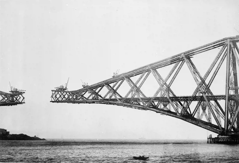
Construction of one of the beam sections that connect two of the Forth Bridge’s giant balanced cantilevers in the 1880s © courtesy of the Institution of Civil Engineers
Bridge to the future
So far as possible, the crossing has been future-proofed. An extra lane or bus lane can be added to the road layout, currently a dual two-lane with wide hard shoulders. The bridge has louvred wind-shielding at 3.6 metres high along its whole length to prevent closure during high winds. A continuous walkway inside the bridge deck will help maintenance be carried out when needed, while the insides of both of the deck boxes and towers are continuously dehumidified to prevent corrosion of the exposed cable anchorages. The cables themselves are well sheathed, but individual strands or even whole cables can be removed, if needed, and replaced without interrupting traffic. The whole bridge is wired up with several thousand accelerometers, anemometers, temperature sensors, corrosion cells, GPS/biaxial tilt meters, and dynamic and static strain gauges so that a picture can be built up of the bridge’s performance in all combinations of wind, temperature and traffic loading. The bridge is intended to last for a very long time.
The whole bridge is wired up with several thousand accelerometers, anemometers, temperature sensors, corrosion cells, GPS/biaxial tilt meters, and dynamic and static strain gauges
Fourth road bridge
💧 Pioneering bridge historical engineering and lifespan preservation through dehumidification
The Forth Road Bridge was designed (jointly with Mott Hay & Anderson) by a team of engineers at Freeman Fox & Partners led by Sir Gilbert Roberts. It was the first in a sequence of bridges that included the Severn, Bosporus and Humber. Forth was one of the many estuarial road crossings that formed part of the reconstruction plans drawn up during the war, but was delayed by post-war austerity. It was 1958 before work could start, and 1964 before it opened: at the time it had the longest suspension span outside the USA at 1,006 metres. Appropriately enough, the joint-venture contractor included Sir William Arrol & Co, the builders of the Forth Bridge.
Much of the technology was borrowed from the USA, where most of the expertise in design and construction of large suspension bridges resided. This included the steel stiffening truss that supported the deck to counter oscillation under sustained wind loading – the revolutionary Freeman Fox aerodynamically shaped steel box-section deck followed later on the Severn.
The aerial ‘spinning’ of the main cables wire-by-wire (32,000 miles of it) was also a well-tested US technique. Each of the two main cables consisted of 11,618 galvanised high-tensile wires, bound into 37 strands, which were then compacted and tied together to form a single two-foot diameter cable. Corrosion protection was provided by galvanising each wire, close compaction, red lead paste, wire wrapping and painting. The weather in the Forth estuary delayed the process: weather losses in cable spinning averaged one third of the total time.
The bridge was designed for a capacity of 30,000 vehicles a day in each direction for 120 years, but as traffic increased to many times this level, concern rose about the bridge’s lifespan. In addition, discovery of corrosion of cables in older US suspension bridges in 2003 prompted an inspection of the Forth’s cables. External inspection had previously shown no sign of problems, and the cables had been regularly repainted, but when sections of the cable were opened up by driving wedges between the strands, a large number of wires were severely corroded, and it was estimated that 8% to 10% of the cables’ strength had already been lost. Furthermore, projections of further corrosion suggested that loading restrictions would need to be put on the bridge by 2014, with full closure a few years later.
An ingenious system for preventing further corrosion was devised, based on the knowledge that no corrosion will occur if humidity adjacent to steel is kept to below 40%. Dehumidification had been used before – including in the cable anchor chambers at Forth – but using the technique for a cable was something of a novelty. The cable was sleeved in a waterproof elastomeric wrap, and then very dry air was pumped in at low pressure through several injection sleeves in each cable, passing along the cable before being released at exhaust sleeves. Further inspections proved the method’s success. A further alarm came in December 2015 when two cracks were found in vertical steelwork of the truss supporting the deck, causing a complete closure of the bridge while repairs were made.
Dehumidification cannot restore strength already lost to corrosion, but it has extended the bridge’s life at full load at least until the opening of the Queensferry Crossing, after which it will become primarily a public transport corridor with much lower loads.
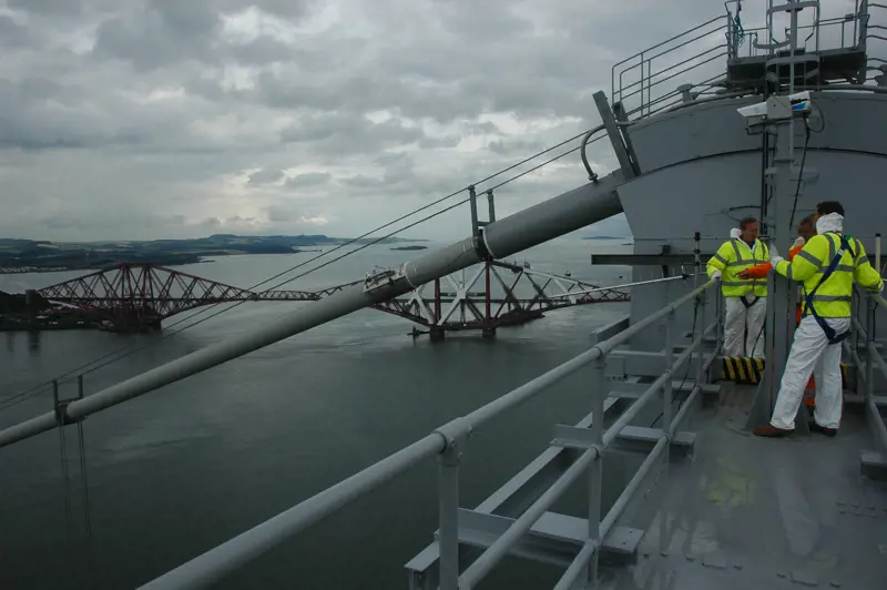
Workers on top of a tower of the Forth Road Bridge in 2010, with the new dehumidification system for the cables in place and work progressing on the ‘final’ repainting of the Forth Bridge in the background © Transport Scotland
Like its neighbours, the Queensferry Crossing has paved the way in innovative engineering, and the three bridges across the Forth should provide a fitting monument to engineering achievement for many years to come.
Simple cantilever bridges, which project horizontally into space and are supported at only one end, are as old as civilisation, but in the late 19th century, engineers began to explore the potential for combining the cantilever principle with steel trusses to span much larger distances, notably on the Forth Bridge.
***
This article has been adapted from "World record-breaking bridge", which originally appeared in the print edition of Ingenia 71 (June 2017).
Contributors
Hugh Ferguson
Author
Michael Martin is Project Director at Forth Crossing Bridge Constructors, the contractors on the Queensferry Crossing Project. He has worked with Arup and Morrison Construction on many of Scotland’s great bridges including Kessock, Kylesku and Dornock Firth Crossing.
David Climie is Project Director for client Transport Scotland and has worked on the construction of many major bridges, including the Forth Road Bridge strengthening, Tsing Ma Bridge in Hong Kong, Storebaelt Bridge in Denmark, and Jiangyin Bridge in China.
Peter Curran is Forth Crossing Design JV’s Director and International Bridge Director at Ramboll UK. He has spent his career with Gifford (now part of Ramboll) on projects including the Gateshead Millennium Bridge and the Twin Sails Bridge in Poole.
Keep up-to-date with Ingenia for free
SubscribeRelated content
Civil & structural

Building the Shard
The Shard is one of London's most iconic buildings. The tallest in Western Europe, it was designed by Italian architect Renzo Piano and dominates the city’s skyline. Ingenia spoke to John Parker, project director for structural engineers WSP, who outlined the engineering decisions made in building the enormous steel and glass structure.

FlexiArch
Arch bridges are strong, durable and require little maintenance. However, very few had been built since the early 1900s until the FlexiArch was developed and launched in 2007. Now, there has been a minor renaissance for this ancient form of construction.

Creating user-friendly buildings
For Michelle McDowell, a former Business Woman of the Year, a passion for joined-up design thinking and building information modelling with a user-friendly approach has enabled her to pioneer revolutionary changes in her field.
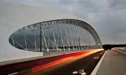
Troja Bridge
In November 2014, one of the world’s largest network arch bridges was officially opened in Prague. The UK may soon have its first network arch bridge if the go-ahead is given for a new rail project in Manchester.
Other content from Ingenia
Quick read

- Environment & sustainability
- Opinion
A young engineer’s perspective on the good, the bad and the ugly of COP27

- Environment & sustainability
- Issue 95
How do we pay for net zero technologies?
Quick read
- Transport
- Mechanical
- How I got here
Electrifying trains and STEMAZING outreach

- Civil & structural
- Environment & sustainability
- Issue 95