Box of Bubbles
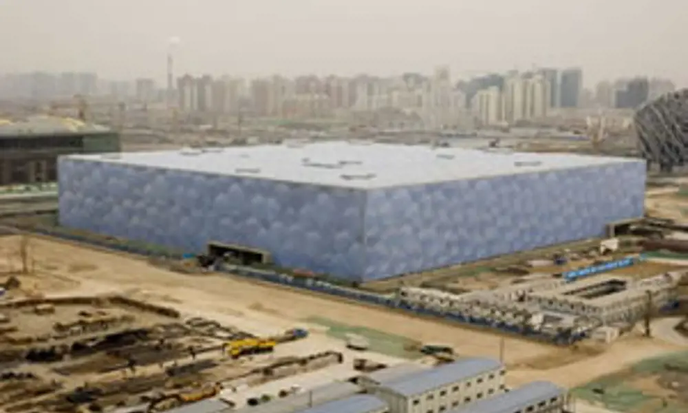
The Water Cube nearing completion. It will be the venue for the swimming, diving, synchronised swimming and the water polo competions in August 2008 © Martin Saunders Photography
The Water Cube swimming hall built for the 2008 Beijing Olympics has already been described as creative, novel and wondrous. Arup Fellow, Tristram Carfrae – based in Australia – describes the concept, the planning and the engineering challenges that enabled the construction of the striking structure.
Early in 2003 the Municipality of Beijing announced a limited design competition for the 2008 Olympic Games Aquatics Centre and short-listed 10 international teams, including our own consortium consisting of the China State Construction and Engineering Company, PTW Architects and Arup.
Unusually, we at Arup began the competition process by outlining to the architects what we wanted to achieve technically, based on our previous experience with aquatic centres; bringing into play a whole gamut of engineering disciplines.
Heat and light
As swimming pools need to be heated for most of the year, we decided that the solution that solved most of the technical problems was an insulated greenhouse. Diffused natural light would enter through a main steel structure built within a cavity, to isolate it from both the corrosive pool-hall atmosphere and from the outside.
Arup also reasoned that ETFE, a transparent form of Teflon, would be most efficient for such a greenhouse, removing the need for a secondary structure and providing better insulation than single glazing. The architectural planning team concurrently calculated that the entire square site would be needed to fit all the required facilities into the centre.
At this time Arup learned of the winning design for the nearby Olympic Stadium, the fantastic curvaceous red ‘bird’s nest’ structure proposed by Herzog and de Meuron/Arup. With this inspiration, we quickly decided the swimming centre should be a contrasting blue box – and so the ‘Water Cube’ was born.
Deciding the look
The prime challenge was to decide which form the structure should take and how the resulting cladding pattern would look. The consortium preferred the notion of a continuous skin that covered the walls and roof alike. Also, we knew that this building needed to be far from ordinary to win this top-ranking commission.
Our team discussed a roof structure of vertical cylinders, clad top and bottom with circular panels. However, circles do not fit well together and we faced the uncertainty of how to progress from vertical cylinders in the roof to horizontal cylinders in the walls without a clumsy intersection. So we asked ourselves: if cylinders do not work, what else will? What sorts of shapes fill three-dimensional space uniformly, besides the somewhat prosaic triangulated space-frame?
I suspected nature would provide the answer, from living cells to mineral crystals. However, after much research I realised that this seemingly innocuous question has no straightforward answer – in spite of the number of natural examples that exist.
Geometrical puzzle
I found I was far from the first to become curious about this particular problem. In the late 19th century the great Lord Kelvin asked: What is the most efficient way to divide space into cells of equal size with the least surface area between them? Kelvin himself proposed a highly regular solution to his own problem. But when we applied the 14-sided Kelvin shape (called a tetrakaidecahedron) it proved visually uninspiring.
Nor was Kelvin the first to seek the solution. A century earlier a Belgian scientist, Plateau, had studied soap bubbles and devised rules for the way they join together in three faces forming a line; four lines coming together at the tetrahedral angle of 109.4 degrees.
Surely it would be simple to create the geometry of a continuous array of soap bubbles? This would in turn answer Kelvin’s question because surface tension automatically minimises the surface areas of the partitions between the bubbles. At this point we again found a ‘But’, because Plateau’s rules simply cannot be applied to create a geometry that joins together.
IT solution
Much more recent research, however, provided our answer. A century after Kelvin, Professor Denis Weaire and his assistant Dr Robert Phelan used advanced computer programmes to help them discover a solution up to two per cent more efficient than Kelvin’s, subsequently named ‘Weaire-Phelan foam’.
We soon found a curious feature about this foam. In spite of its complete regularity, when it is viewed at an arbitrary angle it appears totally random and organic. Today Weaire-Phelan foam has evolved from the computer screen of the theoretical physicist to the actual structure of one of the world’s most novel buildings – the Water Cube.
Our approach to constructing this building began by visualising an infinite array of foam, oriented in a particular way, and then carving out a block the same external size as the stadium, 177m by 177m by 31m. The three major internal volumes were removed from this foam block and the result was the geometry of the structure. This would then be clad with ETFE pillows inside and out to gain the desired organic look and to function effectively as an insulated greenhouse.
Modelling the idea
Our search for the most efficient way of sub-dividing space had led to a structure based on the geometry of an array of soap bubbles, clad with plastic pillows that look just like bubbles – to house the water at the heart of an aquatics centre! Our team were convinced the scheme would win, but crucially we needed to ensure we conveyed the idea effectively to the judges.
We decided to build an accurate physical model of all 22,000 steel tubes (which join at 12,000 nodes) and the 4,000 different cladding panels. Rapid prototyping machinery, more usually used by the manufacturing and automotive industries, seemed to offer the only hope, but no-one had ever made a model this complex.
It took many weeks to learn enough about computer-aided design modelling and the data translation required just to make the structural model. With two days left, the model was flown from Melbourne to Beijing, where it was joined to a hand-made plastic skin – it had proved impossible to draw all the different pillow shapes in time. This completed model helped convince the judges and in July 2003 the consortium was announced the competition winner and awarded the design commission.
The structure
Next came the tricky question: will this concept actually work?
Our entire attention during the competition had focused on the model and we had had no chance to analyse the structure. In fact it had proved impossible to select the size for each individual structural element to obtain a structure that would stand up. So Arup developed new software that would automatically select the member sizes through an optimisation process – and the result is a remarkably efficient structure.
Before long the entire production process became automated. One programme generated the entire geometry from scratch, based on Weaire-Phelan Foam with its challenging characteristics (75% of cells in the foam have 14 faces, the rest have 12 faces… and all have the same volume) and on the size and shape of the building.
Meanwhile the structural optimisation process sized all the steelwork members and their connections, and a specially-written script converted the structural analysis wire frame model into an accurate three-dimensional solid CAD model. Construction drawings and schedules were produced automatically from this 3D model.
By the end of the design phase, we had created a system that would take less than a week to generate a whole new set of construction documents should a major change to the building size or shape be made.
Tubes and bubbles
In Beijing, the structure forms a true space frame in which all members are framed into the nodes. This might seem inefficient in a country not prone to major earthquakes, but for the seismically active Beijing it provides a perfect energy-absorbing structure. Arup decided to make the structure from simple circular tubes welded to spherical nodes at each end to simplify fabrication.
The completed Water Cube building comprises 4,000 ETFE bubbles, some as large as 9m across. Seven different sizes of bubbles feature in the roof and 15 in the walls, repeated throughout. Yet the eye is still deceived into seeing a random pattern. ETFE is a tough, durable plastic that transmits more ultraviolet light than glass and thoroughly cleans itself with each rain shower.
Each pillow is permanently inflated by a low-power pump. This internal air pressure transforms plastic just 0.2mm thick into a cladding panel capable of spanning relatively large distances. In pillow form, ETFE is also a better insulator than glass and provides ‘frit’ (dot) patterns to create shading, thereby achieving the insulated greenhouse.
Fire rating
China’s building code requires a fire rating, achievable by coating the whole structure with a fire spray or a fire-resistant intumescent paint. However, with 90km of steel elements, comprising 6.8 hectares surface area of steel, these options were not satisfactory.
A complex combination of structural and fire engineering analysis showed that for the worse fires the building could experience, the structure would continue to carry the loads without failure – and so no fire protection was needed for the steel.
While ETFE is an amazing material, it is also combustible. To allow the use of this innovative material we addressed concerns about its performance in fire, the potential fire scenarios and the consequences for safety. This allowed us to develop appropriate criteria for material selection to provide an adequate safety level. The greatest attribute of ETFE in fire is that it shrinks away from the heat, thus effectively self-venting and letting smoke out of the building.
Egress and circulation routes were specifically designed to maximise net lettable area, to provide pleasant and efficient open circulation routes and to minimise doors that adversely affect the external architecture.
Fire modelling
With an estimated 20,000 people in the building at any one time during the games, the rigid Chinese code would have required 200m of exit doors – the equivalent of two sides of the building. This would not only spoil the look of the building but also create a security problem. Using international guidelines for sporting venues and through detailed analysis of egress and circulation, the number of exits was reduced significantly.
We used a computer model called Fire Dynamic Simulation to look at how smoke and heat would spread through the building, then tried different smoke exhaust rates in different areas to keep smoke away from people as they move through and leave the building.
Built-in fire safety systems such as sprinklers and smoke exhaust make the building safer for longer – and allow the more open and familiar circulation routes to be used. This is the first time such a major public building in China has been designed using a performance-based fire engineering approach and the design received formal approval in 2004.
Giant greenhouse
The Water Cube is designed to act as a greenhouse. Its ETFE cushions allow high levels of natural daylight into the building and, as swimming pools are predominantly heating-driven, they harness the power of the sun to heat the building and pool water passively. This sustainable concept reduces the pool hall’s energy consumption by an estimated 30%.
The system generates an effective negative U-value or a net energy gain to the building. For this principle to work, the solar load entering the building offsets its heat losses. The use of thermal mass heat storage ensures that the heat the building gains from the sun during daylight is offset by overnight cooling. The thermal mass of the pool water and heavyweight surfaces surrounding the pool effectively stores the excess heat during the day and re-emits it at night, minimising variation in load.
Keeping cool
Variation in shading of the facade has ensured that fabric heat loads are minimised in summer but maximised in winter, when the solar sun is most beneficial. This is achieved by patterning the various layers of the facade with translucent painted ‘frit’ and by ventilating the heat out of the cavity in summer and containing it in winter. The positions and patterns of these translucent elements have been developed to respond to the daylight and the thermal requirements of the various building uses next to the facade.
Energy consumption by the large pool halls is greatly reduced by using the displacement ventilation principle in the mechanical system. The concept of stratification is critical to achieving high passive solar heat gains without generating large cooling loads. By allowing stratification of air in these large spaces, the mechanical system needs only to provide cooling to the occupied spaces, reducing cooling loads; effectively by a factor of ten.
Air-conditioning will keep non-pool and office areas to around 23°C in summertime, with heat rejection of the air-conditioning warming the pools. The leisure pool must be kept at around 30°C while the competition pool requires 28°C.
Air circulation
Swimming-pool centres are very corrosive environments if not designed properly, so air distribution is critical. Due to this building’s unique facade, surface temperature and air movement must be maintained to prevent corrosion. Nozzles are located around the perimeter of the building to supply air up the walls.
During winter, thermal buoyancy lifts warm air to the top. The reverse applies in summer, with cooler air being supplied to compensate for heat gain. This cooler air does not have the same buoyancy force so it will not go all the way to the roof and only condition the lower part of the building. This stratification of air also helps reduce overall energy consumption.
This smart building is designed to be able to create a responsive, comfortable environment. Spectators’ areas, for example, are air-conditioned by an under-seat supply system, which will only be switched on during events. This targets the air-conditioning and prevents wastage to areas not used by spectators and competitors.
Construction
The excavation, footings and basement construction started on site in December 2003. There was a pause in construction during 2004 while the Chinese government reviewed the designs for all Olympic facilities for cost and suitability – fortunately the Water Cube emerged unscathed at the end of this process. The building was successfully contracted for construction at the original, pre-competition budget of US$100 million (including early works).
The critical item for the Water Cube’s construction were the ETFE pillows. These would be the only trade package requiring procurement from outside of China and would consume half the construction budget. A British company, Vector Foiltec, joined forces with a Beijing curtain wall contractor to create the best of both worlds and fabricate, erect, maintain and operate the cladding system for a much lesser sum. The cladding package is due for completion in late 2007 in time for an official opening and test event in 2008 prior to the Olympics themselves.
This aquatics centre – the Water Cube – is a pure delight. It solves all the technical problems in one fell swoop. And it achieves the wonderful, if somewhat coincidental, reality of becoming a building filled with water, made from a box of bubbles.
Biography: Tristram Carfrae
Tristram Carfrae is a structural engineer, Principal Director and Arup Fellow. He is responsible for the design of award winning buildings and is regarded internationally as a leading designer of sporting stadia and lightweight, long-span structures. He was Australian Professional Engineer of the Year in 2001 and in 2006 appointed as a Royal Designer for Industry by the Royal Society for the encouragement of Arts, Manufacturing and Commerce.
Keep up-to-date with Ingenia for free
SubscribeOther content from Ingenia
Quick read

- Environment & sustainability
- Opinion
A young engineer’s perspective on the good, the bad and the ugly of COP27

- Environment & sustainability
- Issue 95
How do we pay for net zero technologies?
Quick read

- Transport
- Mechanical
- How I got here
Electrifying trains and STEMAZING outreach

- Civil & structural
- Environment & sustainability
- Issue 95