Troja Bridge
On 7 October 2013, the last tram rode over a 30-year-old ‘temporary’ bridge over the Vltava. Now, trams, bicycles, pedestrians and general vehicular traffic use the replacement Troja Bridge. The new bridge uses a network arch design that can be elegant, as well as efficient in its use of materials while performing well under dynamic loading.
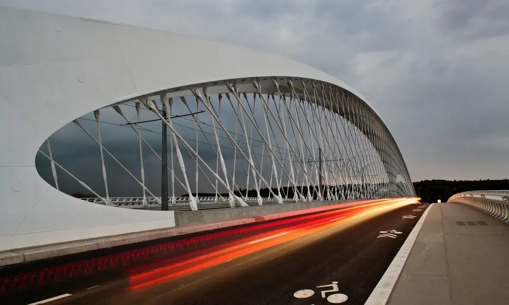
The new Troja Bridge carries trams, road traffic, cyclists and pedestrians across the River Vltava as part of Prague’s Ring Road. The bridge has a span of 200 m, is 35 m wide, and has two particularly striking structural attributes. It has an unusually low arch, with a height-to-span ratio of just 1:10, and the arch itself is extraordinarily slender – just 90-130 cm deep at mid-span.
These two features are made possible by the network of 200 inclined steel rods connecting the steel box-section arch and the pre-stressed concrete bridge deck at 1.8 m intervals which provide stiffness and stability to the structure. This results in a significant economy of materials and allows the arch to be kept very low: just 20 m high, compared with 40 m which would have been needed for a conventional bowstring arch. The result is a network arch bridge that is both elegant and unusually economical in its use of steel and concrete – a saving of 30% compared with a conventional tied, or bowstring, arch.
The new bridge uses a network arch design that can be elegant, as well as efficient in its use of materials while performing well under dynamic loading
Although the concept for a network arch bridge was developed in the 1950s, its potential had not been greatly exploited until relatively recently. The Prague office of the engineering and development consultancy Mott MacDonald had already recognised that this was an underdeveloped concept. It had previously designed four network arch road bridges in the Czech Republic, all with pre-stressed concrete decks, starting with the 41 m-span Bechyně Bridge, built in 2004. Mott MacDonald found that concrete for the deck improves the stability of the bridge, particularly under dynamic loading.
Troja presented an opportunity both to increase the scale, and, in conjunction with architect Roman Koucký, to create a new landmark for Prague. It is now the world’s largest network arch bridge with a prestressed concrete deck – see Network arch origins.
Network arch origins
🌉 The history of the arch bridge
From the mid-19th century, the tied arch, or bowstring arch, was developed. This is a through-arch in which the horizontal thrust is contained by anchoring the ends of the arch to the deck, which then acts as a tension member. The tied arch then behaves very much like a simple beam, requiring its abutments to carry little more than the vertical loads. Even quite large tied arches can be prefabricated, and then craned into position.
In 1955, Per Tveit, a young Norwegian engineer, calculated that, by replacing the conventional vertical hangers of a tied arch with a network of inclined criss-crossing cables, the structure would act like a truss, with the bending moments and shear forces in the arch and deck very much reduced. One important effect is that the arch is restrained at close intervals by the hangers. It is therefore (unlike a conventional arch) not prone to buckling in the plane of the hangers, and can be made very thin: in a conventional bowstring arch either the arch, or the deck, or both have to be stiff. The stiffness, and hence the thickness, of the arch and deck could be reduced, leading to more elegant structures with greater economy of materials.
The network arch is defined as a tied arch with inclined hangers which cross each other at least twice – not to be confused with the Nielsen Bridge developed in Sweden in the 1930s where the inclined hangers do not cross so there is no network effect, or with the heavier bowstring truss (or Belfast truss) where the inclined members are solid and may be in compression or tension.
Tveit presented his findings in his masters thesis. Several of his network arch bridges were built, including the 84 m-span Bolstadstraumen Bridge in 1963 with a steel arch and pre-stressed concrete deck, and others were built outside Norway. Nevertheless, in 2001, Tveit asked “why such a promising type of bridge attracted so little interest”. He blamed the vested interest of steel firms and concrete contractors, unwilling to promote a design that uses less of their materials, and “a constant shortage of engineers who are ready to tackle the intricacies of the network arch”.
Others did subsequently pick up his idea, notably in Germany, the US, Japan, the Czech Republic and Russia, with most replacing Tveit’s pre- stressed concrete with steel or composite decks.

A network arch acts both as a tied arch and as a plate girder, with the arch and the deck to which it is fixed forming the upper and lower flanges of the ‘girder’, and the criss-crossing hangers behaving like an ultra-thin rigid wall, always in tension, connecting the two. The structural elements of a network arch are subjected almost solely to axial forces (with hardly any bending) and therefore their full section capacity can be used. This results in significant economy of materials and allows the arch to be kept very low – Troja’s is just 20 m high
Turning Troja
The hangers on a network arch bridge are naturally pre-stressed by the weight of the structure as the temporary supports are removed. However, initial analysis of Troja confirmed that some of the hangers near the ends of the bridge would switch from tension to compression under certain loading conditions. To avoid this, the hangers of the bridge were ‘tuned’ using a hydraulic device called a ‘techno-tensioner’.
Steel rods were chosen for Troja in preference to cables for the hangers, partly to avoid stretch and give greater control over hanger tension, partly because they are less prone to corrosion
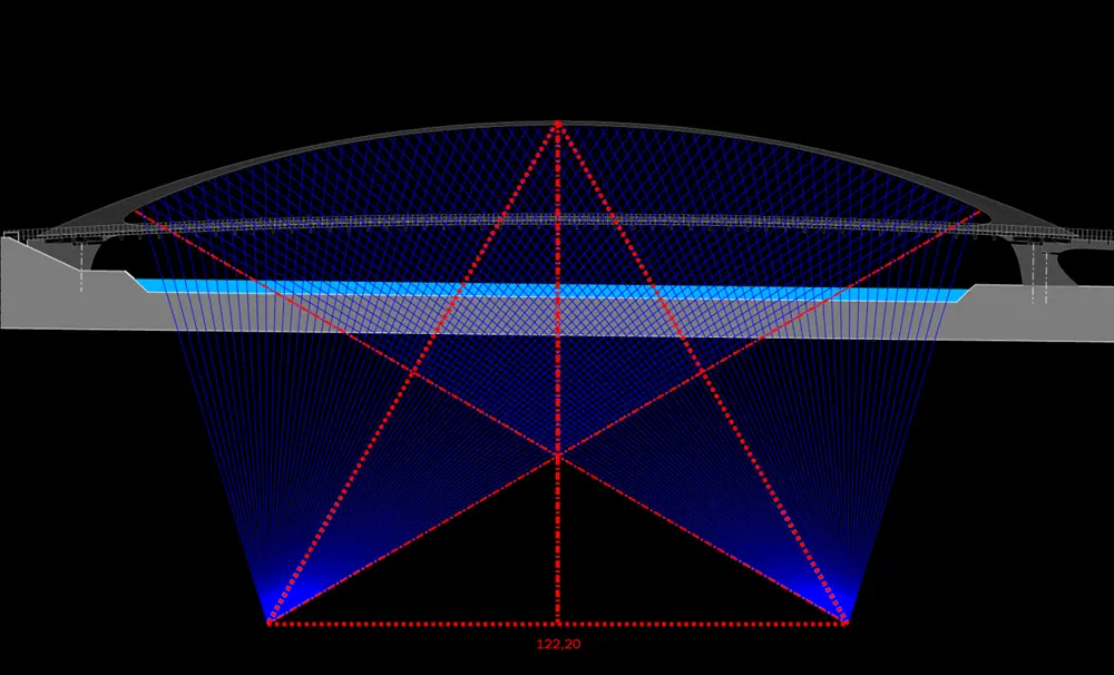
Principle of hanger layout in a network arch bridge. With the Troja Bridge, hangers are arranged in two parallel planes with the slope of the hangers varying: they radiate from two imaginary points beneath the river each about 60m from the centre
The process may be compared to tuning a piano, but with one important difference. Piano strings are supported by a rigid frame: each can be tuned separately, confident that this will not affect other strings which have already been tuned. By contrast, the ‘frame’ of a network arch bridge – the arch and deck – is very thin, and any ‘tuning’ of a single hanger will affect the stresses throughout the bridge, including the tension in adjacent hangers. This greatly complicates the analysis, since no element of the bridge can be designed in isolation. It also means that ways have to be found for measuring accurately and adjusting the load in each hanger.
Steel rods were chosen for Troja in preference to cables for the hangers, partly to avoid stretch and give greater control over hanger tension, partly because they are less prone to corrosion. The rods, in S520 grade steel, were ordered from specialists, Macalloy of Sheffield, complete with fatigue-resistant thread which allowed each rod to be tensioned using a turnbuckle connection. These gauges allow the range and cycle of stresses to be measured in use.
The readings allow the life cycle of the hangers to be estimated, and confirm that fatigue failure – an identified problem with inclined hangers on suspension bridges – is an unlikely problem on network bridges. If needs be, individual rods can be removed and replaced. The bridge is further complicated by its unusual shape, governed as much by architectural as by engineering considerations. For the arch, the engineers required the same stiffness and identical cross-sectional area across its entire length, while maintaining a constant thickness of steel plate: the architect required a shape which changed and flowed across the river. The result is that, in cross-section, the planes of the hangers slope in towards the centre to meet the arch, which is a single polygonal steel box section for the central half of the bridge. This is wide (7 m) and flat near the centre, becoming higher and wider towards the edges before splitting – roughly at the quarter-length points – into a pair of legs at each end, to allow a twin-track tramway to pass between.
The bridge is further complicated by its unusual shape, governed as much by architectural as by engineering considerations
Two long, heavy steel chords connect the bases of the legs across the width of the river, and include the bottom anchor-points for the hangers. A series of 30 m-long, pre-stressed concrete transverse beams are slung underneath the chords, cantilevering out to support two traffic lanes and a footpath and cycle way on each side of the arch, and the chords and beams are integrated by a concrete deck cast on top. Both chords and deck have been pre-stressed longitudinally, so that together they form the ‘bowstring’ which resists the horizontal thrust of the arch, as well as putting the deck itself into compression. This has allowed the deck to be kept exceptionally slim: only 280 mm thick. It has also meant that the abutments are relatively simple, supporting little more than the vertical forces from the weight of the bridge and its traffic.
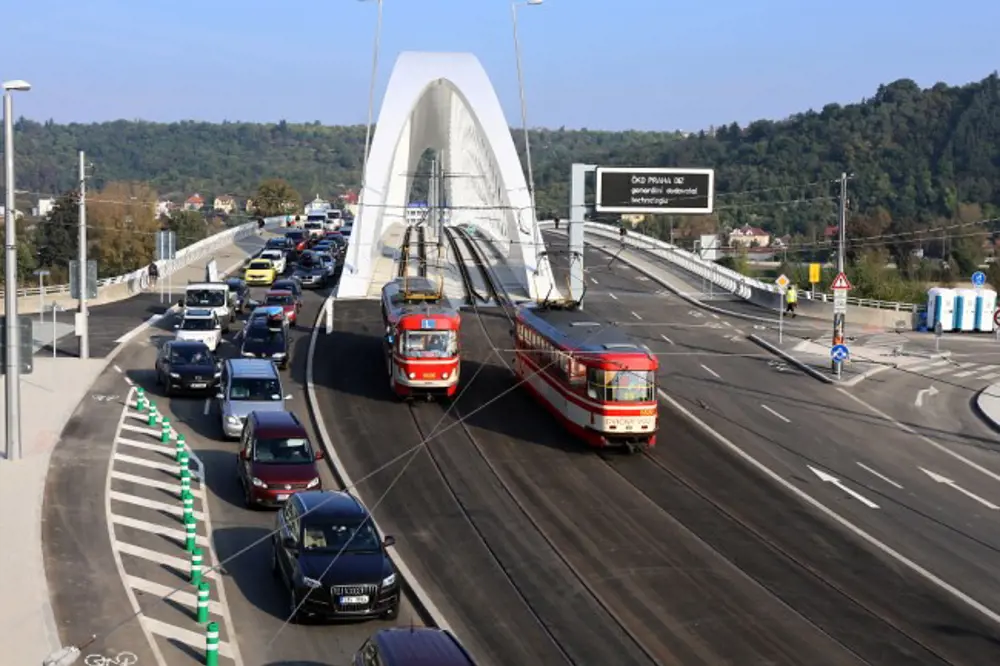
The full 35 m width of the Troja bridge supports four lanes of traffic plus cycleways and footpaths, with the twin tramlines at the centre to minimise eccentric loading. The arch splits towards the ends into four legs to allow the trams to pass through
Construction challenges
Principle of hanger layout in a network arch bridge. With the Troja Bridge, hangers are arranged in two parallel planes with the slope of the hangers varying: they radiate from two imaginary points beneath the river each about 60m from the centre
The contractor, Metrostav of Prague, established five temporary piers erected on piles in the River Vltava, and a temporary steel lattice girder was built on one bank, incorporating parts of the finished bridge. The steel chords formed the upper longitudinal members of the temporary girder, while the concrete transverse beams were slung underneath the chords. Then the girder was launched slowly out across the river until it reached the other bank, and the concrete deck was cast.
The arch was brought to site in small sections, and then site-welded into three larger sections and aligned on the deck. Temporary towers were built up over the piers, to full arch height. Then the three sections were hoisted up – first the two outer ‘windscreen wipers’, then the middle third. Once the arch was complete, and anchored in to the deck, the hangers were installed and tensioned, in a carefully predetermined sequence. Then the girder, and later the temporary piers, could be gradually disassembled underneath. Meanwhile, the longitudinal prestressing of the chords and deck was carried out in three stages: the first third after casting the concrete deck and before the arch erection; the second, after the arch was erected and the bottom chord of the temporary truss had been cut; and the third, on completion of the bridge.
Although load testing of new bridges is rarely carried out in the UK these days, static and dynamic load tests are frequently used in the Czech Republic to verify the actual structural behaviour of the bridge compared to the predicted behaviour. In the static test for Troja bridge, 24 heavy trucks and two 44-tonne trams were placed in different loading positions. The bridge proved to be slightly stiffer than expected: the maximum deflection under the full 911-tonne load at the centre was 51.5 mm, 13% less than the predicted deflection of 59.2 mm. Dynamic tests – with two trucks and two trams driven at different speeds – gave a low dynamic amplification factor of 1.1: in other words, dynamic loads were just 10% higher than the equivalent static loads. Because of the unusual design and the strategic importance of the bridge, a long-term monitoring programme is in place.
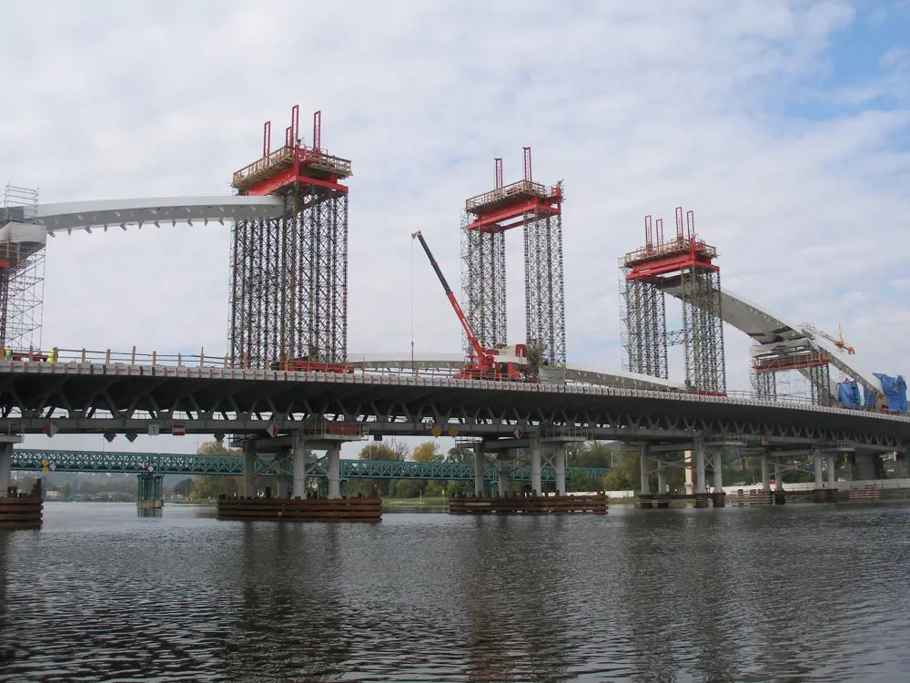
Troja Bridge under construction. The bridge’s steelwork required support during construction. A temporary girder including parts of the finished deck was launched from one end across five piers established in the river. Temporary steel towers were then assembled on top, and the outer thirds of the steel arch hoisted into place
UK's first network bridge
Visualisation of the proposed network arch bridge over the River Irwell which forms part of Network Rail’s planned Ordsall Chord, a short section of new railway in central Manchester. The bridge will be built in weathering steel to reduce long-term maintenance requirements. The varied thickness of the steel plates used means that its area is roughly constant and the asymmetry in its behaviour is reduced
The key to the further development of network arch bridges is computer power, so it seems that the age of network arch bridges may have finally arrived. They are suitable for spans of up to 300 m or so, they minimise material use, they keep deflection to a minimum (particularly important for rail bridges), and they look good: a network arch can be much more elegant than a truss, and not as tall or visually intrusive as a conventional arch or cable-stayed bridge. Construction on the UK’s first – across the River Irwell in Manchester – may start in 2015, with opening to rail traffic scheduled for 2017.
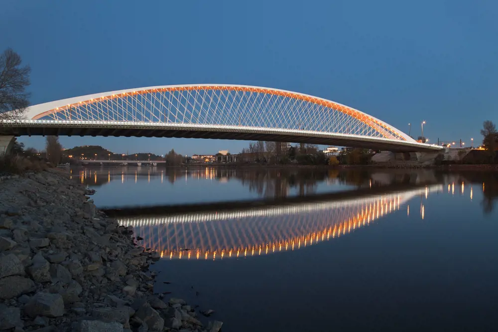
Night view of the elegant Troja Bridge crossing the River Vltava
The bridge will form part of Network Rail’s planned Ordsall Chord, a short but challenging section of new railway in central Manchester, and will carry trains over the River Irwell. While the great 19th century railway engineers linked Manchester to most of the rest of Britain, they neglected to connect the city with itself: in particular, there is no rail connection between the two main railway stations – Manchester Piccadilly in the south east and Manchester Victoria in the north. The Ordsall Chord will provide this vital link.
The network arch not only provides a slender, elegant solution, but it also has engineering advantages for the River Irwell Bridge. Railway bridges need three key qualities. The first is strength – in this case, the ability to carry two fully-laden freight trains moving in opposite directions. The second is limited deflection – to prevent the train from derailing, to avoid passenger discomfort and to prevent damage to the rails. And the third is resistance to fatigue effects from the heavy axle loads. Where the network arch scores very highly is on the second quality: it is exceptionally stiff with very little deflection, and much better than its alternatives.
Though the Ordsall Chord Bridge is much smaller than Troja – 89 m span, 15 m wide (to accommodate a curve in the twin track while keeping the bridge straight) and 14 m tall – it is vastly more complex. This is because Troja was symmetrical, so that the structural behaviour of one end of the bridge is broadly replicated at the other end. For Ordsall, the architects have chosen a variable shape, to connect the structure visually to viaducts at either end: when viewed from upriver, the thickness of the arch tapers from one end to the other.
For construction, the bridge is likely to be built in pieces and assembled onsite, using temporary towers. The assembly may take place, as with Troja, over the river. Alternatively, the bridge may be assembled ‘in the dry’ along the riverbank, and then hoisted into place with a single giant crane lift.
When complete, the bridge will not only be Britain’s first network arch bridge, but also the second-longest in the world to carry twin heavy-rail tracks. If and when the Secretary of State approves the scheme, construction could begin almost immediately.
Improving networks
As experience grows in both the design and construction of network arch bridges, they can be expected to be seen in a wider range of situations. The network arch has advantages in terms of low maintenance and sustainability, where deflections under dynamic loading need to be kept to a minimum. The general form can be also applied to longer spans, and a number of alternative arch geometries could be considered for shorter spans where architectural interest is a key driver.
Construction of these bridges will always be a complicated activity, and designers will need to look to ways where material efficiency is optimised so as to offset the costs of fabrication and assembly.
Recent developments in integrating parametric 3D modelling with analysis are changing all that, and may lead to a renaissance for network arches for medium-span bridges
One of the main obstacles to greater take-up of the network arch has been the complexity of analysis needed, which made the iterations required to optimise designs a long and costly process. Recent developments in integrating parametric 3D modelling with analysis are changing all that, and may lead to a renaissance for network arches for medium-span bridges.
***
The authors would like to thank engineer and freelance writer Hugh Ferguson for his help in compiling this article.
This article has been adapted from "Troja bridge", which originally appeared in the print edition of Ingenia 62 (March 2015).
Contributors
Brian Duguid is the Practice Leader – Bridges, Mott MacDonald FICE, is responsible for coordination and collaboration between all Mott MacDonald’s UK bridge teams. He is also the lead civil engineer for the Ordsall Chord project and lectures in bridge design at the University of Manchester.
Ladislav Šašek is Lead Designer at Mott MacDonald. Šašek is a leading Czech bridge designer who has built more than 100 bridges in 40 years. He was Chief Designer for Prague’s Troja Bridge and a Member of fib Commission 6 on Prefabrication.
Keep up-to-date with Ingenia for free
SubscribeRelated content
Civil & structural

Building the Shard
The Shard is one of London's most iconic buildings. The tallest in Western Europe, it was designed by Italian architect Renzo Piano and dominates the city’s skyline. Ingenia spoke to John Parker, project director for structural engineers WSP, who outlined the engineering decisions made in building the enormous steel and glass structure.
FlexiArch
Arch bridges are strong, durable and require little maintenance. However, very few had been built since the early 1900s until the FlexiArch was developed and launched in 2007. Now, there has been a minor renaissance for this ancient form of construction.

Creating user-friendly buildings
For Michelle McDowell, a former Business Woman of the Year, a passion for joined-up design thinking and building information modelling with a user-friendly approach has enabled her to pioneer revolutionary changes in her field.
Tunnel boring navigation
With no surface reference points, underground surveying requires specialised skills in order to gain trustworthy accuracy for the surveying team. Find out what techniques are used to measure distance, maintain position and cope with curved alignments in tunnels.
Other content from Ingenia
Quick read

- Environment & sustainability
- Opinion
A young engineer’s perspective on the good, the bad and the ugly of COP27

- Environment & sustainability
- Issue 95
How do we pay for net zero technologies?
Quick read

- Transport
- Mechanical
- How I got here
Electrifying trains and STEMAZING outreach

- Civil & structural
- Environment & sustainability
- Issue 95