Cladding Crossrail's tunnels
Laing O’Rourke asked Bryden Wood to evaluate the detailed design and installation of the intended cladding for Crossrail’s tunnels. The company’s findings were so significant that it was commissioned to develop the design and installation principles of the cladding system for three of the largest and most complicated stations – Tottenham Court Road, Liverpool Street and Whitechapel.
The traditional approach for tunnel cladding
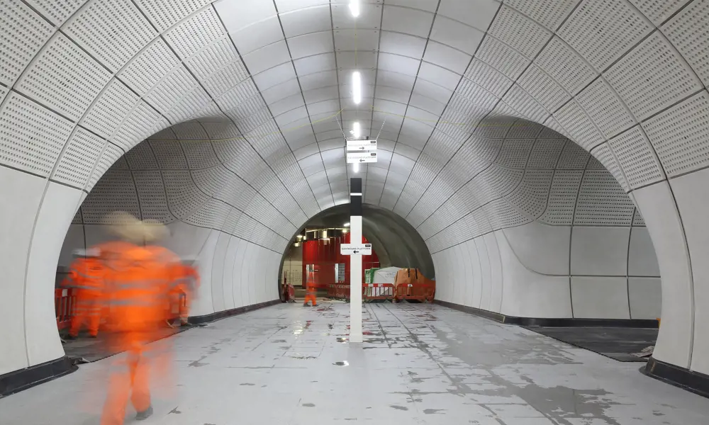
The sprayed concrete tunnel linings for the Crossrail platform and crossover caverns for the stations were applied at an earlier stage of the project. The concrete lining created spacious circulation routes but is not an ideal final finish for the tunnels as it can be inconsistent, dusty, hard to paint and is acoustically ‘bouncy,’ causing sound to clatter and echo. The tunnels needed cables run through for power, lighting, fire detection and alarms, data, and other services, which had to be covered up for aesthetic purposes and to prevent tampering while still allowing access for maintenance and replacement.
On the London Underground, tunnel cladding is normally done with tiles or powder-coated steel panels. Cladding manufacturers and installers contend with vast amounts of variation on construction sites and so systems need to be flexible. General construction allows a ‘plus or minus 10 to 20 millimetres’ level of variability between measurements and production, with the assumption that every fixing (of thousands) will require adjustment. Traditional methods would have risked a slow, labour-intensive and expensive process with a big margin for error. The site was long and narrow, with virtually no room to manoeuvre heavy equipment or stockpile materials. Moreover, constant drilling and fixing into the concrete lining would have created health and safety issues. A new approach was needed.
There were three key aims for the project design: maximum health and safety, maximum productivity and maximum accuracy. This fed into the design of the 23,000 cladding panels. The team aimed to ensure that the detailed engineering and industrial design took place at the beginning of the process. They brought the design team into one office onsite, enabling fabrication design problems to be solved during the planning stages. The key was to get it right first time and then install it once, rather than having to fix things as the project went along.
In contrast to the standard 20 millimetres of tolerance, the team worked with a ‘zero tolerance’ approach to ensure that the manufacturers were as accurate as possible
In contrast to the standard 20 millimetres of tolerance, the team worked with a ‘zero tolerance’ approach to ensure that the manufacturers were as accurate as possible. Although they knew ‘zero tolerance’ wouldn’t be fully achievable, setting such ambitious standards was highly effective, ultimately achieving a 70% tolerance reduction (3 millimetres), when compared to traditional construction. Finally, they used an entirely digital workflow, producing all of the design work in 3D digital formats, eliminating the production of fabrication drawings and potential for human drawing errors. All subsequent reviewing and commenting were also done digitally.
The goal was to develop an engineering solution to minimise fixings into the sprayed concrete lining. The breakthrough solution would create the new ‘zero tolerance’ methodology, provide lighter panels, use less materials, quicken installation and lessen the risk of injuries.
The new cladding system approach
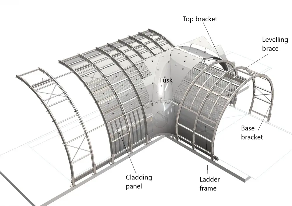
The key elements of the cladding system and the planned sequence of installation were developed in tandem. The solution is a stainless steel ladder framework that holds the glass fibre reinforced concrete (GFRC) cladding panels. The complex intersections where two tunnels meet, known as ‘junction transitions’, required special joining pieces known as ‘tusks.’ Top brackets were fitted to the crown of the tunnel and a levelling brace was attached to the brackets. Next, base brackets were installed to the platform. The ladder frames were then installed between the base brackets and the levelling brace, before finally, the cladding panels could be fitted to the ladder framework.
Design of the lightweight cladding panels
The cladding panels are mostly curved in one plane, although some are curved in three dimensions. A range of panel types were used, some solid and others perforated to include acoustic lining. Cast from GFRC, the panels are composed of tiny, high-strength glass fibres, surrounded by a concrete matrix. The concrete protects the glass fibres and helps carry the load – to some extent acting like the steel reinforcing bars in traditional reinforced concrete. The result is a durable material that can be cast to a very fine and decorative finish but is nearly two-thirds lighter than traditional concrete.
Junction transition: the intersection of two tunnels. The larger one is the platform and the smaller one is the entrance to the platform from a central concourse © Bryden Wood
The lighter panels required fewer fixings and a lighter supporting structure resulting in less load being carried. They also need less material, cost less and emit less carbon in their making. The panels are quicker to make, because thinner concrete sets more quickly, and if light enough, can be manually handled, which eliminates the need for machinery.
Bryden Wood used SolidWorks to develop the design, a software more typically used in manufacturing, product design and industrial design than in construction. This allowed the density of the material to be modelled and the weight and centre of gravity of each panel to be calculated. This led to the lightest possible design that nevertheless safely met all of the technical requirements, with the panels meeting exceptionally high-performance targets for fire, bomb blast and impact resistance. Importantly, the combined weight of the panels and supporting structure met the construction criteria for two-person-handling, eliminating the need for heavy lifting equipment.
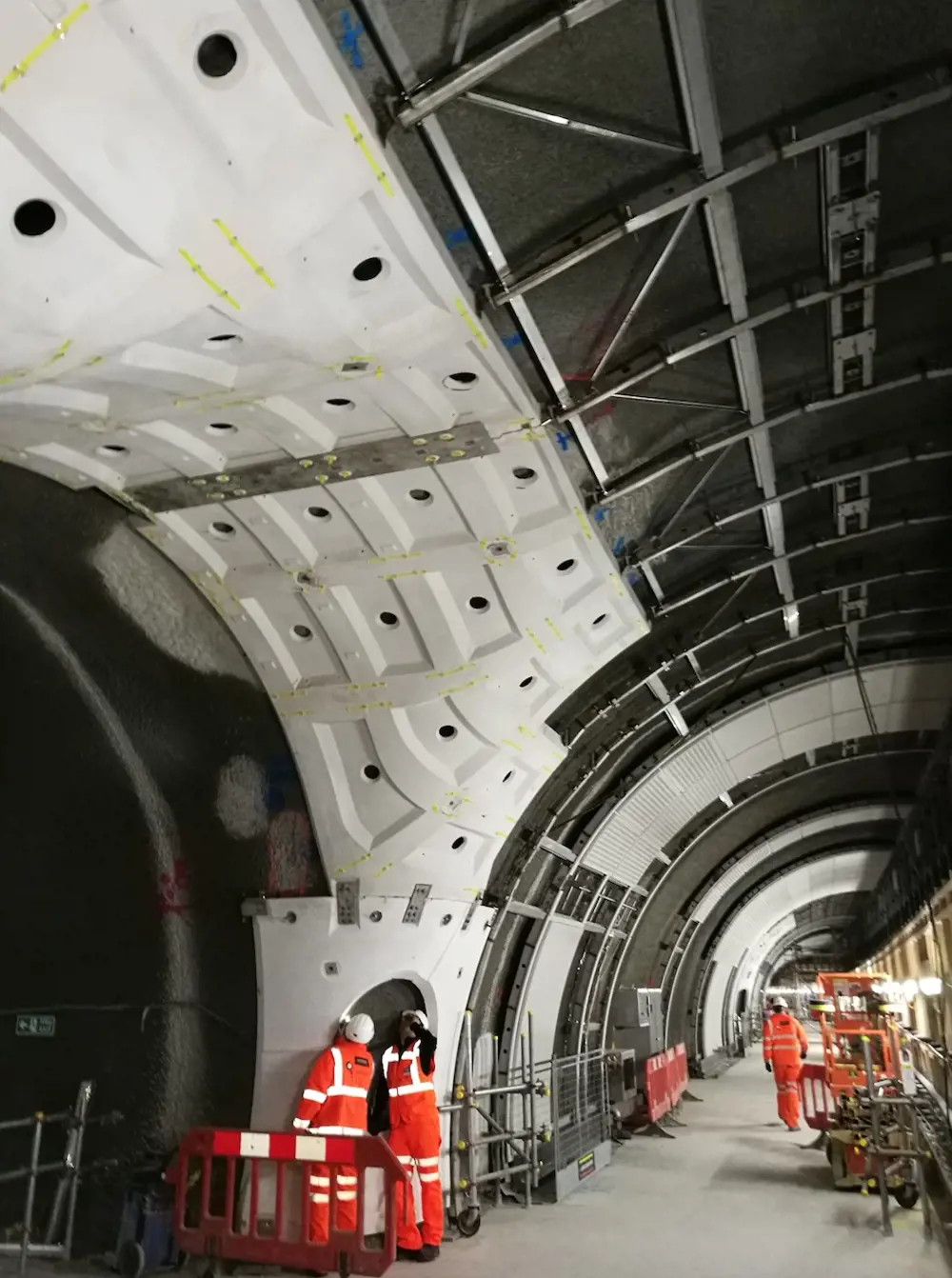
This image shows a GFRC ‘tusk’ in the foreground with the standard ‘ladder’ frame in the background © Bryden Wood
Fixing the panels to support the weight and positioning them accurately
The cladding panels are fixed to a secondary structure to support the weight and to position them accurately. The entire cladding system needed to sit within 250 millimetres of the wall, a challenging proposition when holding several tonnes of concrete in the air.
At the bottom of the cladding, the secondary frame can sit directly on the platform, but the top must be fixed into the sprayed concrete lining, a challenge due to its rough finish and inconsistent thickness. Manually drilling into the concrete, particularly at height, risks injury and is almost impossible to do with millimetre accuracy. The secondary frame overcame the inaccuracy of the concrete spraying and created a highly accurate positioning system for the panels.
The secondary structure is created from steel ‘ladder’ frame structures and cast GFRC arched ‘tusks’, depending on which suited the situation – both have merits. Brydon Wood’s designer Thomas Nunn says “Concrete arches take advantage of the monolithic approach, where you have one complex object that does all the work for you, versus building it out of steel…which also has its merits – they come in small pieces, you can assemble them with less assisted machinery… If one element has a problem, you can replace a small element, rather than having to replace the whole thing or repair it.”
The most commonly-used secondary frame was the series of steel ‘ladders’. Reducing the amount of fixings to the concrete reduced the impact of potential movement of the cladding system over time. Fewer fixings would mean less stress on the system in the event of tunnel movement. To minimise fixings into the sprayed concrete lining, Bryden Wood fixed adjustable brackets to the concrete crown of the tunnel at 4.5 metre intervals to support a levelling brace. This was lined and levelled using a laser beam to ensure it was precisely positioned (+/- 0.0mm) in x, y and z coordinates. This brace would form the support for the top of the ladder frames, so that instead of having to fix every ladder into the sprayed concrete lining, operatives only had to install the single, straight rail – a far easier, safer task.
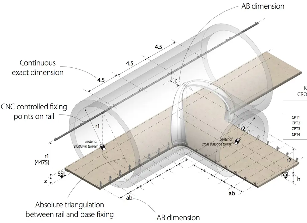
Diagram showing the setting out and installation strategy for the adjustable brackets and rail at the crown of the tunnel and the base fixings © Bryden Wood
For the fixings at the bottom of the frame, adjustable brackets were fixed into the platform rather than the sprayed concrete lining. A laser beam was then fired along the tunnel for the final adjustment to be carried out.
To avoid any issues with corrosion over the planned 120-year life of the project, the specification for the frames stipulated stainless steel. Rather than fabricating the frame, usually done by welding sections of steel together, it was laser cut and folded from a single sheet of stainless steel to ensure accuracy.
Complex shapes, such as the double-curving shape that occurs at the junction of two tunnels of differing diameters, made it too difficult to align and bolt steel elements together in the precise shape required. Instead, GFRC supports with internal high-precision fixing points were cast using moulds. Casting in a single material removed a huge amount of fabrication time and removed the risk of inaccuracy.
Automated mould manufacture for the cladding pannels
During construction, Laing O’Rourke GRC UK Ltd designed and manufactured 2,300 moulds for the cladding panels over a two-year period. Laing O’Rourke used five-axis computer numerical control robotic milling machines, which carved the larger moulds. This process was driven automatically, with Bryden Wood’s models driving the machinery. The mould-making itself was no longer the slowest part – instead it became how quickly the designs for the moulds could be created.
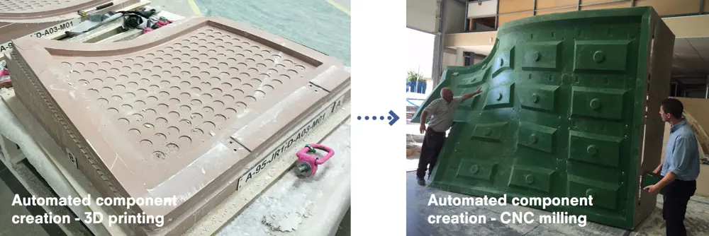
Moulds created directly from the design model. On the left is one of the smaller moulds which could be created using 3D printing. On the right is the mould for one of the tusks – these were computer numerical control-machined from glass reinforced plastic © Bryden Wood
At peak panel production, 350 panels were cast a week to achieve the deadline. A mould was made for each new panel shape, and moulds could be repeatedly sprayed with GFRC. As each tunnel was slightly different, every bend had the potential to introduce an additional 80 to 100 panel types, which could have resulted in hundreds of thousands of pounds of design and mould-making. Digital exercises were carried out to achieve repeatability, using only small tolerances between the panels to take up the variation. The repeatability of panels was a huge cost saving, and the team made a significant effort to try and optimise the shape across the three stations.
A digital installation process
The final steps of the installation process were checked digitally, to avoid issues on site. While most components could be ‘pre-kitted’ and delivered on pallets to site, the larger tusks went through an additional level of checking. Cranes dropped the components down shafts to the platform level below ground. The entire process of delivery to site and the path to site was tested before it happened using virtual models.
When it came to setting out the steel ladder framework, precise coordinates in virtual 3D space were provided down to the millimetre, again generated from the model. Engineers identified the key points on each assembly and standard construction instruments were used to position the key points precisely. With the base bracket positioned accurately, everything fixed to it could be placed in exactly the right position without extra setting out work.
The installation of the architectural feature known as the ‘Trumpet’ at Whitechapel and Liverpool Street station (a large vertical GFRC wall that transitions with double curved panels in the escalator barrels) required two lasers to create a point that indicated where to position the adjustable bracket. The model was clicked on to position the lasers and the installers could then appropriately position the right corner of the bracket onto the cross section.
A new era in construction
This technology and workflow plan has since been applied to precast facades for buildings on the Shell Centre in London and St James’s Place in Edinburgh by Bryden Wood and Laing O’Rourke. On both projects, the digital modelling allowed the most aesthetically-pleasing design to be created and evaluated before manufacture. By using industrial design for fabrication, a digital workflow and automated assembly, the Crossrail cladding package was delivered on budget and on time, while also improving health and safety.
The focus on efficiency and innovation delivers standardisation. Gradually, projects such as this are leading the industry towards a new era
The focus on efficiency and innovation delivers standardisation. Gradually, projects such as this are leading the industry towards a new era. Without compromising aesthetic integrity, architects and engineers are now looking towards a future of building faster, more economically and with better whole-life value.
***
This article has been adapted from "Cladding Crossrail's tunnels", which originally appeared in the print edition of Ingenia 81 (December 2019).
Contributors
Tamar Collins
Author
Jaimie Johnston is Board Director and Head of Global Systems at Bryden Wood, where he leads the adoption of a manufacturing-like approach to creating high performing assets on projects.
Sam Bromley is the Design Director of Element Design & Consulting. At the time of writing, he was a design engineer at Bryden Wood, with specialist experience in sheet metal, timber, and structural steel.
Thomas Nunn is a mechanical engineer who worked on the project using high-quality computer-aided-design.
Keep up-to-date with Ingenia for free
SubscribeRelated content
Civil & structural

Building the Shard
The Shard is one of London's most iconic buildings. The tallest in Western Europe, it was designed by Italian architect Renzo Piano and dominates the city’s skyline. Ingenia spoke to John Parker, project director for structural engineers WSP, who outlined the engineering decisions made in building the enormous steel and glass structure.
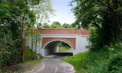
FlexiArch
Arch bridges are strong, durable and require little maintenance. However, very few had been built since the early 1900s until the FlexiArch was developed and launched in 2007. Now, there has been a minor renaissance for this ancient form of construction.

Creating user-friendly buildings
For Michelle McDowell, a former Business Woman of the Year, a passion for joined-up design thinking and building information modelling with a user-friendly approach has enabled her to pioneer revolutionary changes in her field.
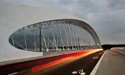
Troja Bridge
In November 2014, one of the world’s largest network arch bridges was officially opened in Prague. The UK may soon have its first network arch bridge if the go-ahead is given for a new rail project in Manchester.
Other content from Ingenia
Quick read

- Environment & sustainability
- Opinion
A young engineer’s perspective on the good, the bad and the ugly of COP27

- Environment & sustainability
- Issue 95
How do we pay for net zero technologies?
Quick read
- Transport
- Mechanical
- How I got here
Electrifying trains and STEMAZING outreach
- Civil & structural
- Environment & sustainability
- Issue 95