Francis Crick Institute, London
Engineering research
👩💻 What analysis was done prior to construction?
Considerable modelling and analysis was carried out on the building before construction began, including:
- Acoustics and vibration – background acoustics and vibration levels were measured and then used as the baseline for compliance and mitigation measures.
- Electromagnetic compatibility/interference – the profile of the site was assessed in order to establish background levels, as much of the research equipment is sensitive to electromagnetic emissions.
- Environmental studies – a number of studies were performed, including the impact the building would have on existing air quality.
- Daylighting – studies were performed to identify the impact that the building would have on its surroundings. This focused mainly on the housing around two sides of the site, looking at its rights of light and the amount of natural daylight entering the buildings.
- Thermal performance – the building was modelled with specialist software to confirm compliance with building regulations and to support the sustainability assessment.
- Dispersion modelling – numerical analysis to confirm that the 32 large extract air stacks and thermal flues would be compliant with emissions requirements, and wind tunnel tests to confirm that emissions would not re-enter the fresh air intakes.
- Odour modelling – conducted using both numerical and empirical testing of biomedical research facility (BRF) waste materials on exhaust streams. Mitigation mainly by filtration and dilution.
Named after the molecular biologist who, together with his colleague James Watson, identified the structure of DNA in 1953, the Francis Crick Institute is one of the largest biomedical research facilities (BRF) in Europe. It represents a particular partnership between its six founders, each of which has a long and distinguished association with biomedical research: the Medical Research Council; Cancer Research UK; the Wellcome Trust; University College London; Imperial College London and King’s College London.
The institute’s vision is “to discover the biology underlying human health, improving the treatment, diagnosis and prevention of human disease”, and its work will address seven fundamental questions such as how a living organism acquires form and function, and how the immune system knows whether, when and how to react.
The new laboratories will draw together the founding partners’ existing research activities, hence the choice of location close to leading London hospitals and institutions, in the middle of a well-established research community with excellent transport connections. The founding organisations wanted not only the highest-quality state-of-the-art facilities and equipment, but also a layout that encourages collaboration and cross-fertilisation between researchers across a broad range of disciplines including biology, chemistry, physics, engineering, computing and mathematics, and discourages isolated ‘ivory tower’ projects. They were also keen to encourage turnover of researchers and projects, providing a continuous injection of fresh energy and ideas, and to provide a facility that would be adaptable to new emerging scientific opportunities.
The founding organisations wanted not only the highest-quality state-of-the-art facilities and equipment, but also a layout that encourages collaboration and cross-fertilisation between researchers across a broad range of disciplines
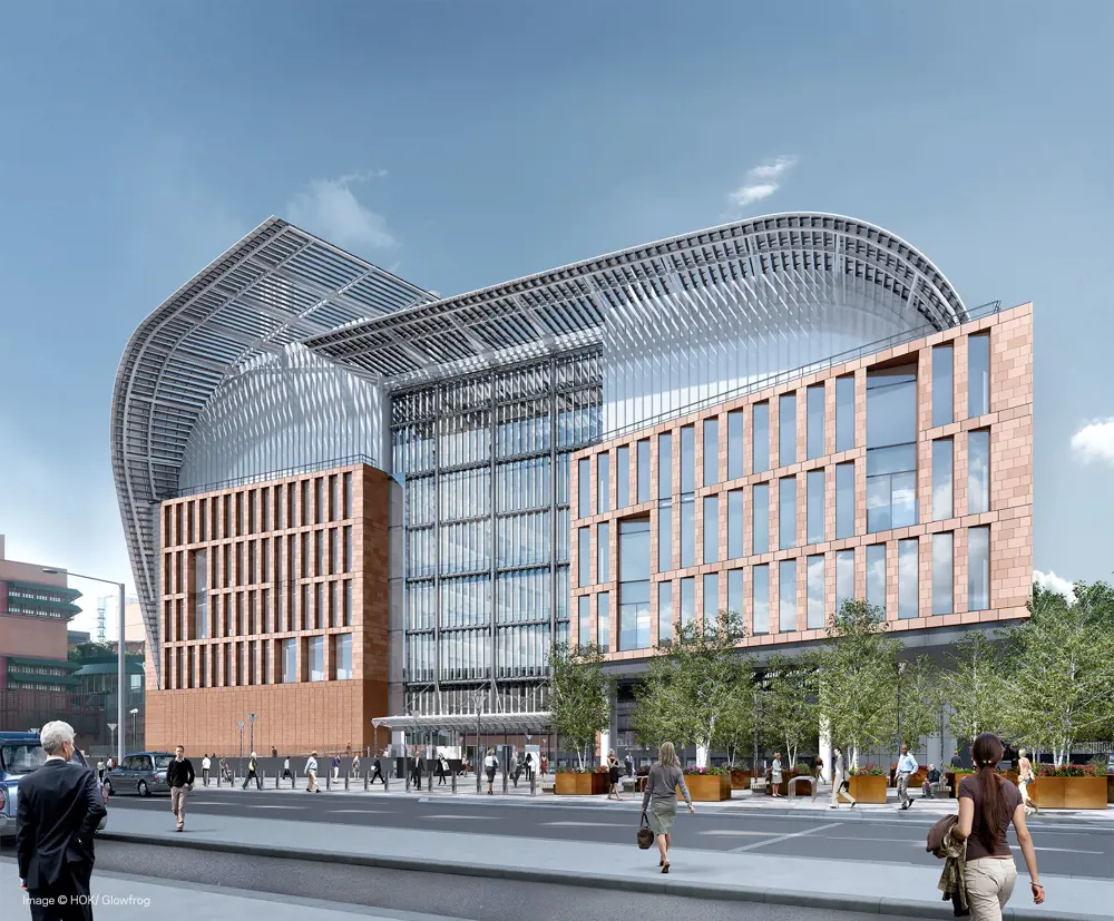
The main entrance to the Francis Crick Institute, viewed from St Pancras International Station, with its glass, steel and terra cotta façade and its distinctive curving steel roof © HOKGlowfrog
The building’s design team worked closely with the scientists to turn their ideas into reality, which included challenging some of the initial design requirements. For example: some of the impossibly high rates of air change requested for laboratories were reduced to manageable but perfectly adequate rates; and high vibration resistance, required for laboratories containing sensitive equipment, was extended to all laboratories at the suggestion of the design team in order to provide greater adaptability for future use.
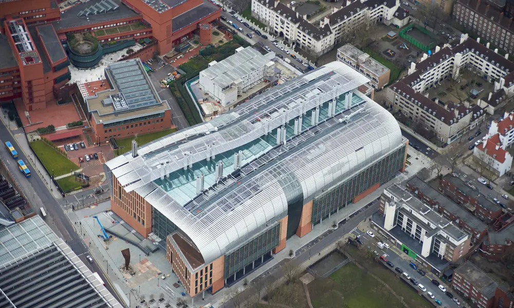
For the last four years, the institute’s new building has been taking shape behind the British Library and alongside St Pancras International station, and later this year, the first of some 1,500 scientists and support staff move in. It is by any measure a huge building, with 83,000 m2 of space spread over 12 storeys, four of them below ground in one of London’s largest basements. But what makes it so unusual is the combination of engineering measures required to meet the exacting requirements of state-of-the-art biomedical research in a city centre building. Unprecedented levels of mechanical and electrical services have been provided to maintain the required environments within the laboratories, and in particular to safely contain the hazardous materials and bacteria involved with such research. Extraordinary measures have been taken to reduce vibration and magnetic permeability of the building to avoid affecting sensitive equipment.
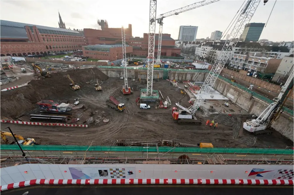
The basement being excavated down to 8 m depth, ‘in the open’ to facilitate removal of old Victorian brick and concrete, and with a deep, thick cantilevered concrete retaining wall to protect the sensitive old infrastructure round the sides. At the bottom, a concrete slab was cast and some 260 piles were sunk. Then, construction started on the building above, while simultaneously the remaining two levels of basement were excavated and concreted beneath © AKT II
Construction plan
Inside the front entrance, the largely open-plan laboratories lead out onto wide full-height atria that separate the four laboratory blocks, creating a calm and spacious environment. Behind are some of the high-containment laboratories that require a controlled environment. Beneath in the basement are the biological research facilities (BRF), more high-containment laboratories and all of the most sensitive research equipment.
The large size of the basement – covering an area of approximately 150 m x 70 m and making up almost a third of the building’s size – was governed by the space requirements and limitations on the height of the building due mainly to the need to retain rights of light for the housing on two sides. As so often happens in London, digging down meant negotiating existing infrastructure. This included: two 120-year-old low-pressure cast-iron gas mains to the north; old brick-arch sewers to the north and west; the British Library’s buried pumping station to the south; and the buried structure of St Pancras Thameslink station to the east, which also provides support for the new roof of St Pancras International station. The site itself was a former railway goods depot built in the 1880s, and was underlain by a dense grid of brick footings on mass concrete, to a depth of 8 m in places.
The traditional and most straightforward way to construct the building would have been to use ‘bottom up’ construction: complete the full excavation within propped retaining walls, sink piles as foundations, and then build the structure up from the bottom. A much quicker (but more expensive and riskier) way would have been ‘top down’: sinking plunge piles from ground level, casting the ground-floor slab, and then simultaneously building upwards, supported by the piles, and downwards between the piles to create the basement. This technique was used for construction of The Shard.
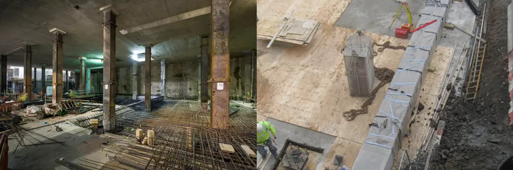
‘Top-down’ construction for the lower two basement levels, with heavy steel plunge columns supporting the building above while the basement is excavated and concreted beneath. Close to the magnetically-sensitive NMR spectrometers, the steel columns were replaced with precast concrete plunge columns incorporating austenitic stainless steel reinforcement, which reduced magnetic permeability by a factor of around 100 © AKT II
After several design iterations, a compromise was chosen: conventional excavation down to the second basement level, which allowed the old masonry and concrete footings to be removed, and then ‘top down’ from there. This solution depended on being able to support the excavation down to 8 m depth in the temporary condition, with only minimal lateral movement of the surrounding ground; even small differential movement could have caused the sensitive St Pancras escalators to jam, or allowed the cast-iron gas main to crack and cut off gas supplies to Camden. The answer was a 1 m-thick heavily reinforced concrete diaphragm wall around the perimeter of the excavation, sunk to a depth of up to 28 m and acting as a free cantilever to support the excavation over the top 8 m. The thickness and strength of the wall kept horizontal movement during construction within acceptable limits, without the need for additional propping. Ground movements were modelled beforehand with a full 3D nonlinear finite element analysis, and carefully monitored during construction.
Some 260 cylindrical hollow steel piles, generally of 900 mm to 1900 mm diameter, were then sunk from the level two basement deep into the Thanet Sands some 40 m below ground. The soil inside each pile was excavated down to below the lowest basement level, and steel box-section plunge columns of up to 600 mm x 600 mm were lowered down inside, and concreted into the piles at the bottom. Upward construction could then commence, supported by the plunge columns. Meanwhile, as the lower two basements were excavated the cylindrical steel pile casing could be removed and the exposed plunge columns encased in concrete.
Vibrations
🏗️Protecting the NMR and MRI scanners from vibration
The Francis Crick Institute has been constructed with a remarkably high resistance to vibration, but the NMR and MRI scanners in the basement required an additional level of protection.
Modern laboratory equipment can accept only extremely low levels of vibration transmitted within the building structure, and the design team agreed early on with the scientists to provide a high Vibration Criteria-A (VC-A) level across all laboratory floors, to allow maximum future adaptability. This limits the vibration threshold to just 50 microns per second – approximately 16 times stricter than the typical limit for commercial spaces. External sources of vibration such as road traffic and trains were measured at ground level before construction: analysis suggested that the sheer mass of the building with its deep basement would absorb most of this movement, and this was confirmed by measurement after construction. All internal sources of vibration were identified and mitigation provided. For example, all engineering plant that could generate vibration has been isolated from the structure by means of anti-vibration mountings, spring hangers and supports. This left the vibration caused by people moving round the building as the most significant factor for the design of the structural slabs, and various combinations of footfall with singles or groups, fast or slow walking, were analysed. The greatest single measure to reduce the effects was to design a heavier and stiffer structure than would be needed for loading alone – for example, concrete floor slab thicknesses are 400 mm minimum rather than 300 mm.
A huge complication came from the decision by main contractor Laing O’Rourke to prefabricate as much as possible of the concrete structure, rather than building in situ. This had clear advantages in terms of programme, cost and the quality control that could be achieved in an off-site factory environment, but meant that the vibration response of the structure could be critically affected, particularly by the location of joints between precast units and the form of the joints. Never before had this technique of precast construction been proven in a facility with such stringent vibration limits.
A rigorous modelling exercise was carried out using a combination of analysis software and in-house interface coding to prove that the vibration limit could be met. Different support conditions, damping effects and ranges of applied modes were tried out with alternative mesh densities and material properties to balance the theoretical results with an expected reality.
Results suggested that while the precast behaved in a similar way to the in situ, there was generally a slight decrease with the precast in the structure’s ability to resist vibration, so further detailed design using finite-element analysis was carried out to reverse the trend. Measures adopted included tailoring the precast detailing and interfaces to align with the behaviour of the building’s structural frame, optimising the layout of panels, fully grouting all joints, and maximising the concrete strength.
The highly sensitive equipment in the basement, such as the NMR spectrometers, required far higher levels of vibration protection: up to VC-F, which is more than 15 times as strict as VC-A. The basement floors are stiffer than those at upper levels, but nevertheless the equipment needed special mountings to achieve the required levels. Each NMR sits on a heavy mass-inertia concrete base supported by a tuned spring system, to isolate it from any movement of the basement structure.
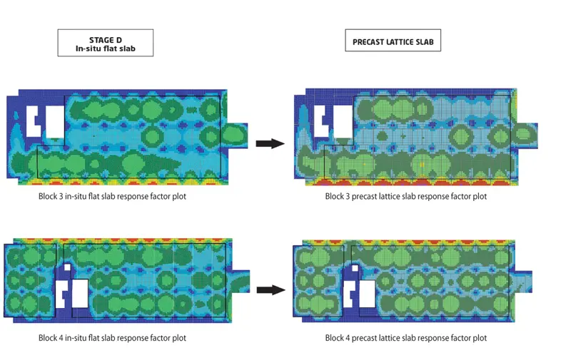
Results of the vibration analysis of the floors, comparing the response of an originally planned in-situ concrete flat slab (left) with the as-built precast lattice slab © Arup
Protected research equipment
However, much of the research equipment is very sensitive to electromagnetic emissions. Most sensitive of all are the five nuclear magnetic resonance (NMR) spectrometers, which can help determine the details of the electronic structure of molecules by measuring the intramolecular magnetic field. Because of their weight and the need to minimise vibration, these had to be located deep in the basement. Located close by are two similar but smaller magnetic resonance imaging (MRI) scanners and various superresolution imaging microscopes, electron microscopes and cryoelectron microscopes (similar, but where samples are studied at cryogenic temperatures). Sources of radiation that could affect these instruments included railways and traffic, radio and TV broadcasts, lifts and the engineering plant. Mitigation measures included shielding the equipment rooms with aluminium, additional active cancellation systems, and filtering all power supplies entering the rooms.
In a typical biomedical laboratory in a less urban location, the sensitive equipment might be housed in a light, single-storey building. In the Crick’s basement, the equipment rooms are surrounded by a heavy structure packed with steel to support a multi-storey building overhead, with high magnetic permeability that had to be reduced. Consequently, in these areas, conventional reinforcing steel in the concrete floors and walls was replaced with epoxy-coated stainless steel, which has much lower magnetic permeability, and all secondary steel (such as purlins to support ceilings) was replaced with inert materials such as fibre-reinforced polymers.
Mitigation measures included shielding the equipment rooms with aluminium, additional active cancellation systems, and filtering all power supplies entering the rooms
This still left the problem of the heavy steel plunge columns close to the spectrometers. The solution, devised by contractor Laing O’Rourke, was to replace the conventional steel columns with precast concrete plunge columns incorporating austenitic stainless steel reinforcement, which reduced the magnetic permeability by a factor of around 100. At 14 m long and weighing 15 tonnes, these were the largest ever manufactured off-site and they were so successful that precast is likely to replace steel for plunge columns on some future projects, even where magnetic resonance is not important.
The sophisticated equipment in the lower basement level also posed another complication. At the heart of each of the five NMR spectrometers is a liquid helium-cooled superconducting magnet, with the liquid helium held in a vacuum at cryogenic temperatures. In the unlikely event of a failure of the vacuum, the helium would ‘quench’, vapourising to gas at nearly 800 times its liquid volume over a short period. This would have needed additional large diameter ducts from basement to roof to provide emergency venting for each spectrometer room. To avoid this, the NMRs have been housed together in a large basement chamber of some 2,000 m³ that has been designed to safely deal with a quench from any one before the conventional air-handling system takes over.
Focus on air handling
As the cross-section through the building and the 3D services model reveal, the building is packed with engineering services. Two of the four basement levels and three of the eight above-ground levels are almost entirely filled with services, and indeed the building resembles a massive industrial plant with some working space sandwiched in between.
Dominating the engineering services are the air-handling facilities. The units on the upper floors suck in some 400 m3 of fresh air per second and discharge through an array of stacks along the spine of the building – equivalent to emptying an Olympic-sized pool in less than 10 seconds. The BRF area in the basement has particularly high ventilation requirements, driven by a combination of conditions for hygiene and heat dissipation: some 20 air changes per hour have been used, combined with careful contaminant control, provided by a combination of architectural design and the ventilation regime.
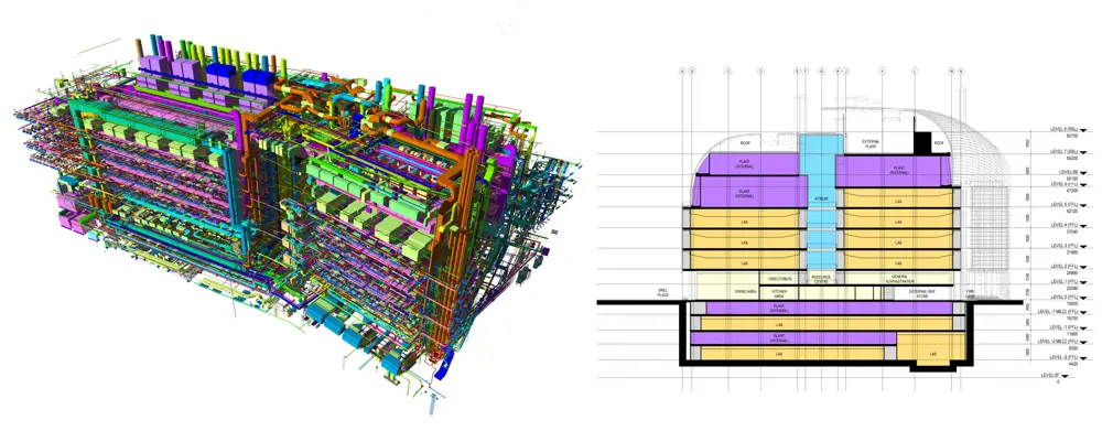
A three-dimensional building information model of the complex and extensive engineering services, so that the building resembles a massive industrial plant with some working space sandwiched in between. As the cross-section through the building shows, two of the four basement levels and three of the eight above-ground levels are mainly filled with services © Arup
The high-containment laboratories, where for example experiments may be carried out on viruses that are resistant to antibiotics, require particularly rigorous control and are subject to licensing by the Department for Environment, Food and Rural Affairs (Defra). These laboratories are constructed as sealed units within the building structure, with a constant negative air pressure so that any air movement would be fresh air entering the laboratory rather than air escaping, and with high efficiency particulate arrestance (HEPA) filtration of both air supplies and exhaust. They are subject to strict safety checks by the Health and Safety Executive and must pass rigorous design reviews, called Hazop analyses, as well as quantitative risk assessments for the highest level of containment.
Occasionally these laboratories have to be fumigated, which is achieved by the most effective means known: a 40% solution of formaldehyde in water is boiled in the room, killing all germs but at a concentration more than a hundred times higher than the fatal dose for humans. Careful control of the process, including the safe dilution and exhaust of the gas, is clearly critical. In particular, stainless steel ductwork is used, with torqued gaskets at joints to prevent any leakage.
With such large volumes of air being discharged, emissions from the stacks carrying the exhaust air have been numerically modelled, as well as the flue discharges from the gas- and oil-fired boilers and the building’s combined heat and power (CHP) generators. Discharges must satisfy both the Clean Air Act 1956 and the local authority with regard to contamination at local street-level receptor points. A physical model was tested in a wind tunnel to check that no discharges are returned into the building. This combination of numerical modelling, wind tunnel testing and physical measurement was a novelty at the time the building was being designed, though careful planning of discharges from buildings has become more common since.
Engineering throughout
Air handling was not the only complication in the engineering services. For example, water had to be supplied in different forms: domestic hot and cold water; separate laboratory hot and cold water; softened water for autoclaves and other sensitive equipment; reverse osmosis water; blended softened water; on-floor treated water supplies; and, in the BRF area, a specialist aquatic life-support system. Similarly the main gas supplies include liquid carbon dioxide to provide gaseous CO2 throughout the building, liquid nitrogen and compressed air, and a network of gas manifolds provide flexibility of specialist gas provision. Consequently, the ‘plumbing’ of the building is exceptionally complex, requiring (in addition to the plant floors) large vertical distribution risers running the height of the building, with horizontal primary routes for services connecting between risers at each floor level. A state-of-the-art building information model (BIM) was used to coordinate services runs and minimise clashes, led by the building’s principal architect, HOK.
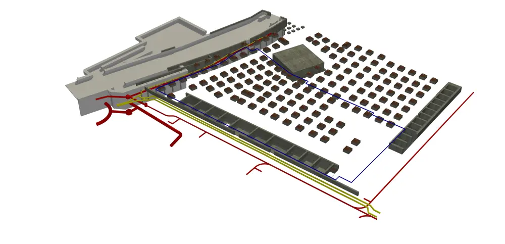
The site was constrained on all sides, with the buried structure of St Pancras Thameslink platforms to the east (left of picture), two Victorian cast-iron gas mains to the north, old brick-arch sewers to the north and west, and the British Library’s buried pumping station to the south. The site itself was once a railway goods depot, and was underlain by a grid of brick footings on mass concrete which had to be removed © AKT II
The project team
🗂️ The project manager, architects, engineers and consultants who worked on the project
Client:
Francis Crick Institute
Project manager:
Arup Project Management
Architects:
HOK, with PLP and BMJ
MEP engineer:
Arup
Cost consultant:
Turner & Townsend
Structural engineer:
AKT II
Main contractor:
Laing O’Rourke
Many of the building’s systems are duplicated or backed up to provide additional security. If the power and gas supply fails for the whole building and diesel deliveries are suspended for the dual-power boilers, the building is designed to run fully for two days, followed by a gradual controlled rundown – an unusually strict fail-safe procedure governed by the Home Office. This requires a 7.5 MVA standby generation capacity, and a 300,000-litre diesel fuel storage.
Visitors to the Crick may appreciate the striking architecture of the building with its geometric terracotta blocks topped by two flowing, overlapping curved steel roofs, or they may wonder at the cutting-edge research being carried out within. However, very few will comprehend the extraordinary engineering that has gone into its construction.
***
This article has been adapted from "Francis Crick Institute London", which originally appeared in the print edition of Ingenia 67 (June 2016).
Contributors
Hugh Ferguson
Author
Steve Berry is an Associate Director at Arup and Building Services Design Team Leader for The Francis Crick Institute, where he is responsible for the delivery of the mechanical, electrical and plumbing (MEP) systems. Steve joined Arup in 1988 and obtained a degree in engineering in 1992. Since that time, he has worked with the firm in Germany, Russia, Thailand, USA and Denmark.
Rob Partridge is a Director at structural and civil engineering practice AKT II, and is responsible for leading a diverse range of projects, both in the UK and internationally. His portfolio includes: The Francis Crick Institute with HOK International and PLP Architecture; the Eli and Edythe Broad Art Museum, USA, with Zaha Hadid Architects; and the Whiteleys development in London with Foster + Partners.
Keep up-to-date with Ingenia for free
SubscribeRelated content
Civil & structural

Building the Shard
The Shard is one of London's most iconic buildings. The tallest in Western Europe, it was designed by Italian architect Renzo Piano and dominates the city’s skyline. Ingenia spoke to John Parker, project director for structural engineers WSP, who outlined the engineering decisions made in building the enormous steel and glass structure.

FlexiArch
Arch bridges are strong, durable and require little maintenance. However, very few had been built since the early 1900s until the FlexiArch was developed and launched in 2007. Now, there has been a minor renaissance for this ancient form of construction.

Creating user-friendly buildings
For Michelle McDowell, a former Business Woman of the Year, a passion for joined-up design thinking and building information modelling with a user-friendly approach has enabled her to pioneer revolutionary changes in her field.

Troja Bridge
In November 2014, one of the world’s largest network arch bridges was officially opened in Prague. The UK may soon have its first network arch bridge if the go-ahead is given for a new rail project in Manchester.
Other content from Ingenia
Quick read

- Environment & sustainability
- Opinion
A young engineer’s perspective on the good, the bad and the ugly of COP27

- Environment & sustainability
- Issue 95
How do we pay for net zero technologies?
Quick read
- Transport
- Mechanical
- How I got here
Electrifying trains and STEMAZING outreach

- Civil & structural
- Environment & sustainability
- Issue 95