Going underground underneath London’s Claridge’s hotel
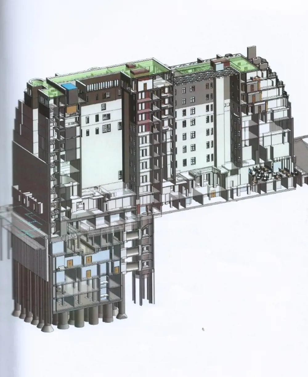
A cross-section through the front of the hotel shows the new basement below the art deco extension that was added in the 1920s © Arup
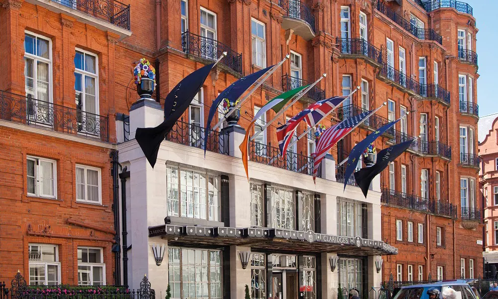
Claridge’s hotel in Mayfair, once described as the ‘first hotel in London’ and later as ‘an annexe to Buckingham Palace’ because of its strong royal connections, opened in 1856 as an amalgamation of five terraced buildings. In the 1890s, it was built and redesigned in its current form, and a large extension, encompassing 80 new rooms and a ballroom, was added on the east side in the 1920s. However, in order to thrive as a top five-star hotel in the 21st century, the hotel needed more rooms and more facilities, including a spa and a swimming pool. For planning reasons, building upwards was out of the question, so extending downwards became the preferred solution. The real challenge came from the need to keep the hotel open and fully functioning throughout the building works: a temporary closure would risk regular visitors changing their loyalties before the hotel reopened.
In 2015, the Maybourne Hotel Group asked engineering firm McGee to create a five-storey basement beneath the art deco extension. McGee was the only contractor to believe that the work was possible without closing the hotel, but realised that help was needed to confirm that it could be done without endangering the building overhead, so Arup was brought on board as geotechnical and structural engineering consultant.
The real challenge came from the need to keep the hotel open and fully functioning throughout the building works
A family affair
🏗️ How the Claridge’s project brought Jim Mackey out of retirement to work with his daughter on construction
In 2007, Wembley-based McGee was invited, along with several other civil engineering contractors, to submit a proposal to extend the basement beneath Claridge’s by two storeys. Managing Director Jim Mackey devised and proposed a scheme that would keep the hotel open throughout: all the other contractors required the hotel to close during the works.
But the 2008 recession and disputes over the hotel’s ownership intervened and the scheme went into cold storage. Meanwhile, Jim retired in 2015 and resettled with his wife in Ireland.
A few weeks later he was sitting at home when the phone rang. It was Claridge’s. The project was once again live, only now the hotel required five storeys instead of two: “We want you to do it, and it starts next week.” Jim returned to London, initially just to start the project up, but he got too involved and has stayed throughout, enlisting the help of his daughter as senior engineer.
Michelle Mackey had not intended to follow her father into construction. After graduating in mathematics from the University of Southampton and gaining a master’s in statistics the following year, she took a job in research. But she found that she was getting bored. It was only then that Jim suggested engineering, and she enrolled at London South Bank University to complete a civil engineering course part time.
The two make an effective team, with complementary skills and experience. With the Claridge’s basement complete, will Jim now return to retirement? It seems there may be just one more project for the pair to work on together.
Stabilising the building
The 1920s eight-storey extension is supported by 61 steel columns resting on a 1.1-metre-thick, 50 metre by 25 metre reinforced concrete raft (a slab spread out under the entire building) directly below the lower ground floor, with no pile foundations beneath. Some distance beneath the raft was firm London Clay, but unfortunately in between the raft and the clay were treacherous, uneven layers of gravel, up to half a metre thick, overlain by saturated silt with a high water content up to two metres thick, which was an alluvial flood plain feature of the former course of the River Tyburn. In its contained state, this silt had a high bearing capacity and could satisfactorily support the building overhead. However, once disturbed, below the water table the material flowed like ‘running sand’, or where it was a clayey silt, it behaved like toothpaste. Either way, both would damage the existing raft if a novel solution could not be found to address this ground risk.
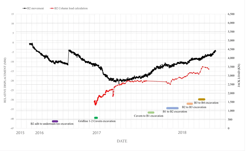
Measurements of loading (red line – from January 2017 when loading was transferred to the new columns) and displacement (black line) at the top of one of the 61 new columns at the base of the existing building, during construction works up to September 2018. The various construction activities are indicated beneath. The graph shows that, during top-down construction (B1 to B4 excavation), heave forces acting on the underside of the caisson foundation have been pushing this column upwards since October 2017 (black line), with a corresponding increase in the load in the jack, from what the engineers consider to be heave pressure © Arup
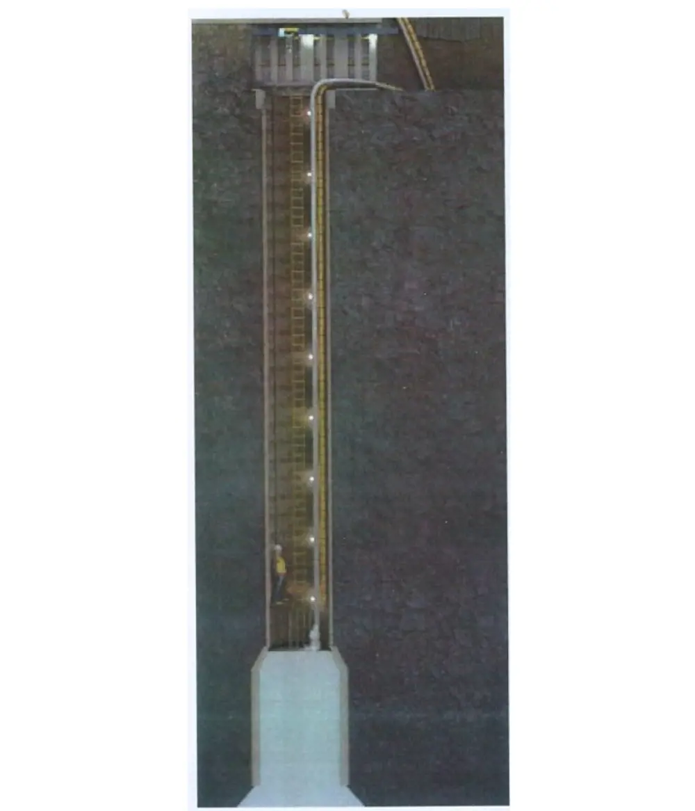
One of the 61 hand-dug caissons with a temporary steel lining, widened out below the bottom of the new basement where it was backfilled with concrete to form a new pile © McGee
Arup and McGee came up with a plan to create the new basement:
- Stabilise the silt, then carefully excavate a series of strongly supported tunnels directly underneath the raft, with a group of horizontal passages running from the tunnels to provide access to the points directly beneath each of the building’s columns.
- Hand-dig 61 caissons (large, watertight retaining structures), up to 30 metres deep, below the raft.
- Fill the bottom of each caisson with concrete to form new piles up to the underside of the new basement.
- Construct reinforced concrete columns within the caissons, up from the top of the piles to the bottom of the raft.
- Transfer the load from the existing building onto the new columns, so relieving the loads on the raft.
- Gradually excavate downwards through the clay to create the basement levels, casting new walls and floors on the way.
As if this was not challenging enough, the work had to be done with no noise or disturbance to the occupants overhead. The team was initially allocated just one small room on the lower ground floor (with a second room and a connecting corridor added later). All excavated material had to be removed, and all material and equipment brought in, through one window at the rear of the building, and lifted with a single hoist through one small hole in the raft. There was virtually no storage space, so all deliveries and removals had to be carefully planned on a ‘just in time’ basis. No noise, vibration or other disturbance to the hotel above could be tolerated. With a ‘live’ building overhead, the safety and stability of the structure at every stage was critical.
With the raft, the concern was not so much whether it would sink or even tilt during the work, but whether it would bend and crack, and if so, where and how
Given the uncertainties, the engineers’ approach was to adopt several different methods of analysis producing different results, enabling sensible judgements to be made about the loads and deflections that the concrete raft could safely withstand. As a ‘worst case scenario’, it was assumed that the concrete could develop potentially large cracks in areas of high flexural stress and low (or no) reinforcement. Punching shear – often a governing design criterion in modern raft design, which is the tendency of the column with its large point load to ‘punch’ a hole through the raft – was less of an issue because of the ability of the existing grillages (an arrangement of metal beams to create large steel feet) at the base of each column to spread the concentrated column loads. The main strength analysis methods adopted were Johansen yield line analysis and an arching model, which took advantage of the non-simultaneous excavations to develop thrusts through the surrounding raft. Engineers assessed deflections using tools ranging from simple geometrical models of strain (taking into account the high ductility found through testing the mild steel rebars) through to sophisticated 3D finite element cracked concrete time-history analysis. The edges of the slab were a particular concern, including the effects of load redistribution in the existing masonry walls. Overall, the analysis gave confidence that loading at every stage could be kept within the acceptable ultimate loads – provided that deflections due to excavation were controlled and could be measured – and that the chosen approach was feasible and safe.
A 3D finite element geotechnical model of the raft’s interaction with the ground was subjected to different excavation activities (tunnel excavation, shaft caisson construction, removal of temporary steel, and soil removal beneath the raft) to predict possible raft movements. This was vital to informing structural models and analysis. This was a project where the structural and geotechnical engineers relied on an integrated approach to design to provide a unique solution.
Overall, the analysis gave confidence that loading at every stage could be kept within the acceptable ultimate loads – provided that deflections due to excavation were controlled and could be measured – and that the chosen approach was feasible and safe.
The first two challenges were to gain an understanding of the existing concrete raft and how it would behave at every stage of construction until its eventual – very different – role as a suspended slab, and to find a way to deal with the saturated silt immediately below the raft.
A two metre by two metre hole was cut through the raft, both to provide initial access and to enable samples of the concrete to be analysed and tested. The hole was later doubled in size to provide the main access route for materials.
With the raft, the concern was not so much whether it would sink or even tilt during the work, but whether it would bend and crack, and if so, where and how. Tests on the sample confirmed that the concrete was good quality. Desk studies from the time of the extension’s construction unearthed reports that 75 tonnes of steel had been used in the raft – slightly more than the relatively light reinforcement found in the sample would suggest. The probable explanation was that ‘additional’ reinforcing steel is located beneath the columns.
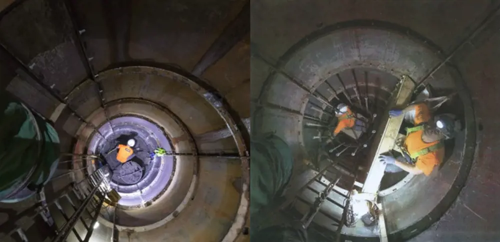
A miner hand excavates one of the 61 steel-lined caissons (left), while another places a reinforcing bar for a new column within the tight space of a hand-dug caisson (right) © McGee
Quiet excavation
Several methods of dealing with the silt were considered. Grout injection, which is usually used to fill accessible pores between the solid particles in a soil to strengthen it, was not suitable because the material was too dense and clay-like to inject. Ground freezing to stabilise the saturated silt was also rejected because it would have required access to occupied hotel rooms, meaning that the hotel would need to be closed and was therefore outside the client brief. Tests showed that the silt, once dried, formed a remarkably stable clay-like material, so engineers decided to drain the silt using vacuum pumps from several bored wells. First, the perimeter of the site had to be sealed on all four sides to stop more water flowing in. The most challenging part was the north side along the front of the hotel, where no external construction work could be permitted. The solution was a ‘water cut-off beam’ beneath the edge of the raft, 1.2 metres wide by 1.8 metres deep (to connect into the impermeable clay below) and 25 metres long, created by digging a tunnel using vacuum draining along the edge of the raft, and then filling with reinforced self-compacting concrete.
Now excavation beneath the raft could begin – but very carefully to ensure that only small areas of the raft were left unsupported at any time. Miners dug the first tunnel of 1.8 metres by 1.8 metres in section with stiff steel frames every 500 millimetres to transfer the load from the raft above to the ground beneath. Passages were then excavated out from the tunnel to reach the points directly beneath the hotel’s columns, from where the caissons would be sunk.
Two miners used pneumatic spades to hand-dig each circular caisson through the dried silt and clay, installing a temporary lining formed of one-metre-deep bolted steel segments as they progressed. The diameter of the caissons was a critical decision: miners needed sufficient space to work and, at a later stage, to install the formwork and reinforcing steel for the new concrete columns, working in the cramped annular space between the columns and the caisson walls. However, the span of the raft that could be opened up to form the top of the caisson had to be kept to a minimum. A ‘sweet spot’ of 1.8 metres diameter was eventually chosen.
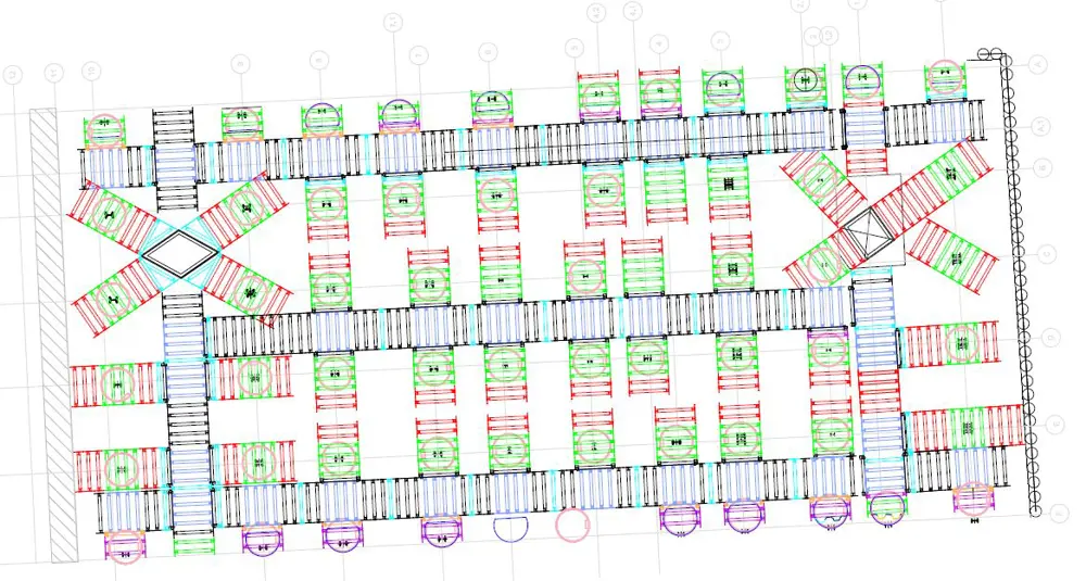
A diagram shows the three main tunnels (in blue) – named Tom, Dick and Harry – beneath the concrete raft, with numerous access tunnels to connect to the heads of each of the 61 caissons © McGee
A hotel floating on hydraulic fluid
🏨 The key to the safe construction of Claridge’s new basement
Key to the safe construction of Claridge’s new basement was the close monitoring of loads and deflections of the existing hotel at every stage of the work, together with the ability to make adjustments to the load distribution if the measurements approached a critical level.
Engineers primarily measured deflections through a real-time monitoring system that was established by installing automatic liquid levelling sensors on each of the 61 columns of the 1920s building, just above the raft, which could tell within one millimetre the vertical position of each column. Sinking of the whole building or upwards heave during construction, even quite substantial movement, or tilting of the slab were of little concern: much more serious was differential movement between the various columns, implying curvature and bending in the raft that could cause cracking.
The initial concern was the effect of draining the silt immediately under the slab, but at every subsequent stage there was potential for differential movement, particularly as the sequencing of the work meant that construction was not progressing evenly across the whole site.
The early works saw less movement than had been expected, and no damage to the building overhead. In particular, the sinking of the caissons caused little movement as the temporary tunnel frames provided support against the underside of the raft and the caisson rings were grouted in place to minimise ground loss.
As each new column was completed, two 800 tonne hydraulic jacks were installed at the top to connect with the raft and existing columns above, which provided the ability to adjust loading and height on each column as required. Two jacks were required because the maximum travel was only 28 millimetres per jack, and it was expected that larger movements up or down would need to be made. Activating the jacks had the effect, not so much of pushing the hotel upwards, but of pushing the columns and piles downwards and absorbing the initial elastic settlement. Engineers measured loading simply by reading the hydraulic pressure in the jacks. Movement or changes in load did not happen suddenly, so there was time to monitor trends, check them against trigger limits set by the design, and plan any remedial action. At various stages of basement construction, excavation caused the ground below to heave, and load had to be removed from some of the jacks to maintain stability.
The jacks are still in place and active, and will be until all possibility of unacceptable movement has passed. In the meantime, the whole art deco extension on the east side of Claridge’s remains floating on hydraulic fluid.
When the miners reached the bottom of the new basement 22 metres beneath the raft, the diameter was increased to 2.7 metres and more conventional, permanent precast concrete linings of up to four to six metres in depth were installed for the next section. Finally, the bottom of the excavation was ‘belled out’ to a diameter of up to 4.6 metres to form a broad, flat base for the new piles. The level of the bottom of each pile was carefully chosen to avoid going below the impermeable London Clay, which would have allowed groundwater to enter and required compressed air working. Reinforcing steel was placed and the caissons were then concreted to form solid piles, up as far as the bottom of the new basement.
Working upwards from here, formwork and reinforcing steel were installed and the concrete poured for the 600-millimetre diameter permanent columns, founded on the new piles and running up the centre of the caissons. At the top of each new column, engineers installed twin 800-tonne hydraulic jacks and used them to start transferring the load from the existing building into the new foundations. The jacks, together with associated measuring equipment, were used to monitor loads and movement, and to make adjustments when necessary.
The first six caissons and columns were treated as ‘trials’ to prove the feasibility of the proposed method, and only after their successful completion did the project turn into a full-blown contract. Tunnelling beneath the raft was extended, with three main tunnels – named Tom, Dick and Harry after the tunnels in The Great Escape – running most of the length of the raft, and with passageways connecting to the heads of all 61 caissons. There were so many tunnels and so much activity that it reminded those on site of an Indiana Jones movie.
With all 61 columns complete, the jacks were operated to transfer an additional load into the columns, equivalent to about three quarters of the dead load of the building. With the building’s load now removed from the raft, the network of tunnels and passageways could be removed and excavation of the basement could commence, dismantling the temporary steel caisson rings and adding new concrete walls and a basement slab linked into the new columns. The first basement was completed in February 2018.
***
This article has been adapted from "Going underground", which originally appeared in the print edition of Ingenia 77 (December 2018).
Contributors
Hugh Ferguson
Author
Jim Mackey
Project Director, McGee
Michelle Mackey
Project Engineer, McGee
Dinesh Patel
Director and Geotechnical Engineer, Arup
Andy Pye
Associate Director and Structural Engineer, Arup
Keep up-to-date with Ingenia for free
SubscribeRelated content
Civil & structural

Building the Shard
The Shard is one of London's most iconic buildings. The tallest in Western Europe, it was designed by Italian architect Renzo Piano and dominates the city’s skyline. Ingenia spoke to John Parker, project director for structural engineers WSP, who outlined the engineering decisions made in building the enormous steel and glass structure.
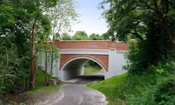
FlexiArch
Arch bridges are strong, durable and require little maintenance. However, very few had been built since the early 1900s until the FlexiArch was developed and launched in 2007. Now, there has been a minor renaissance for this ancient form of construction.

Creating user-friendly buildings
For Michelle McDowell, a former Business Woman of the Year, a passion for joined-up design thinking and building information modelling with a user-friendly approach has enabled her to pioneer revolutionary changes in her field.
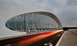
Troja Bridge
In November 2014, one of the world’s largest network arch bridges was officially opened in Prague. The UK may soon have its first network arch bridge if the go-ahead is given for a new rail project in Manchester.
Other content from Ingenia
Quick read

- Environment & sustainability
- Opinion
A young engineer’s perspective on the good, the bad and the ugly of COP27

- Environment & sustainability
- Issue 95
How do we pay for net zero technologies?
Quick read
- Transport
- Mechanical
- How I got here
Electrifying trains and STEMAZING outreach

- Civil & structural
- Environment & sustainability
- Issue 95