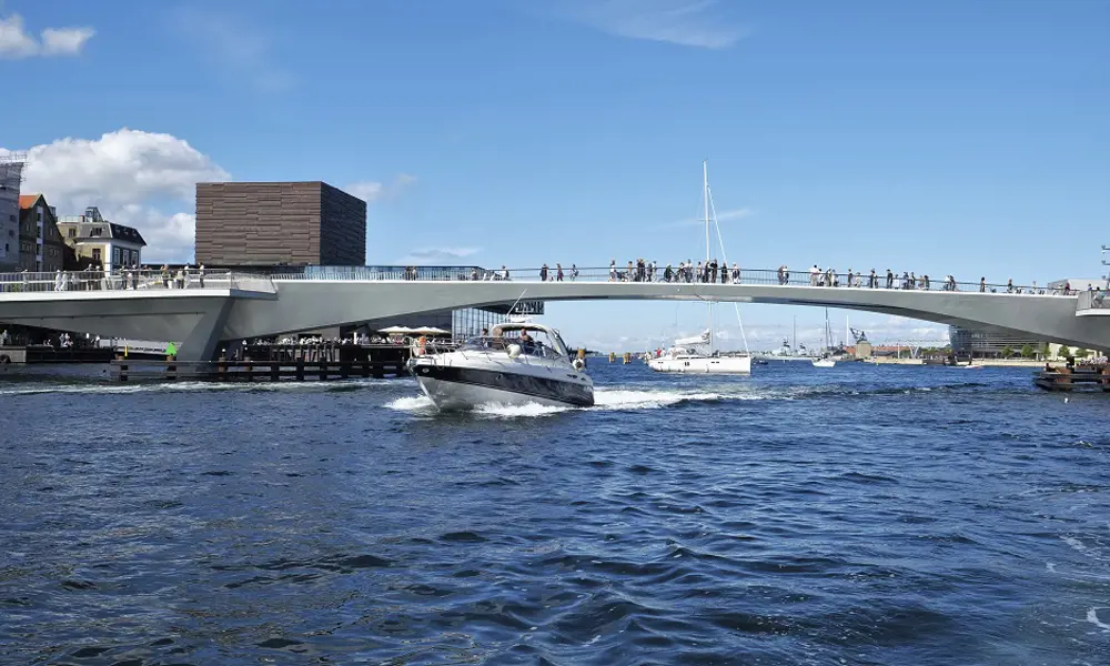
Copenhagen's 'kissing' bridge
Copenhagen is not a city that is short on bridges, but one was needed to link the heart of the city with Christianshavn in the east, an area that is undergoing substantial development and is home to Henning Larsen’s famous new Opera House. In 2009, a design team led by engineering consultancy Flint & Neill (now COWI) won an international design competition for a new, opening pedestrian and cycle bridge over Copenhagen’s Inner Harbour. Ten teams competed to design a new crossing in this historic setting and to create what would become the first bridge encountered by anyone entering Copenhagen harbour from the sea.
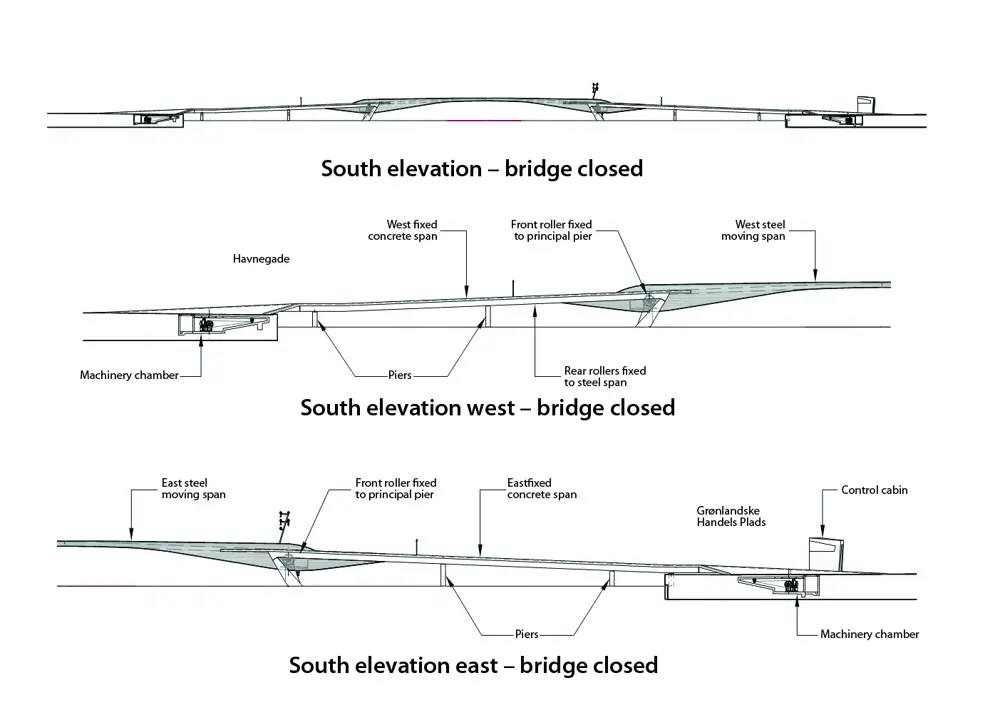
The bridge’s sliding spans are cantilevering, steel box girders. Their undersides follow a smooth wave-like profile in elevation to provide the greatest structural depth at the support where the bending moment is largest. The structural depth then tapers to only 600 millimetres at the cantilever tip at midspan, where the two girders meet and interlock
Aside from COWI, the team comprised architects Studio Bednarski, mechanical and electrical designers Hardesty & Hanover, and lighting designers Speirs & Major Associates. Working in a close collaborative team, the designers came up with the innovative sliding bridge idea in response to the geometry and character of the site. The idea of a bascule bridge (drawbridge) was dismissed as the designers felt that it would be an excessive visual intrusion on Copenhagen’s cityscape when raised. Similarly, a swing bridge was avoided as it would have compromised free passage of vessels in adjacent canals. The required navigation channel opening was narrow compared to the overall harbour width, making it possible to withdraw the opening sections in a sliding manner and create a functional and innovative bridge.
The concept for the bridge was decided early in the process and the initial sketches reasonably reflect how the final bridge looks. Principal engineer Amar Bahra led the day-to-day design activity throughout the project. He worked regularly with Studio Bednarski to discuss the concept and develop ideas, and was in close contact with Hardesty & Hanover in New York. From the very early stages, the designers coordinated efforts to create a structure that was conceived as a closely worked combination of architecture, structure and mechanism.
Each time it opens, two curved, steel box girders slide apart and then back again to gently meet at the centre – hence its nickname, Kyssebroen or the Kissing Bridge
There are other sliding bridges across the world that focus more on functionality than design. The team wanted to bring that sliding method of opening to an architectural pedestrian bridge that would create a surprise for onlookers who would expect the moving spans to raise or swing rather than slide. Each time it opens, two curved, steel box girders slide apart and then back again to gently meet at the centre – hence its nickname, Kyssebroen or the Kissing Bridge.
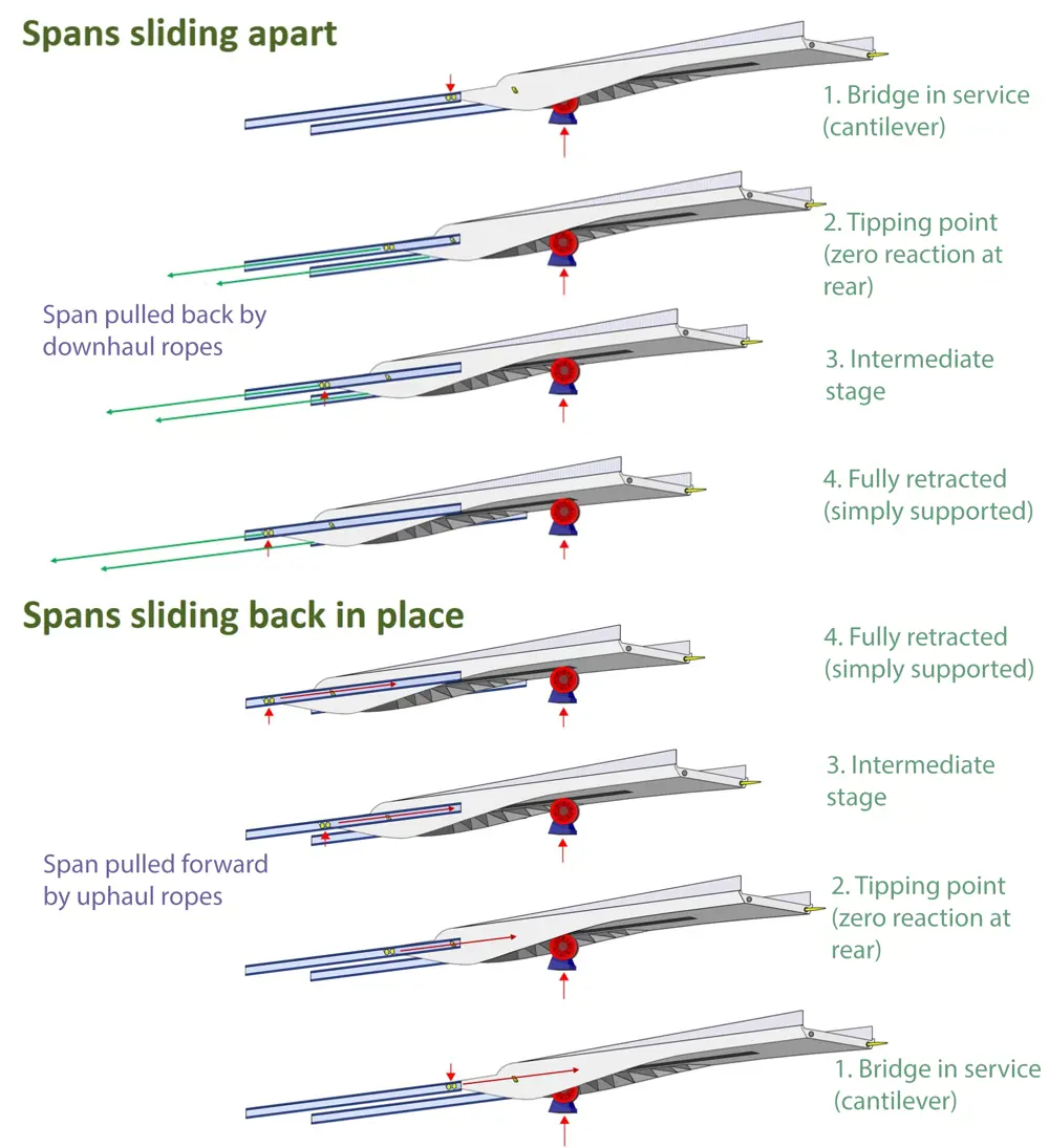
Top: The front roller and tracks are fixed, so stay where they are while the spans are pulled back. The tipping point is when the centre of gravity of the moving span passes the front roller and the rear support reaction goes to zero and reverses. This continues until the span is fully retracted. Bottom: The winch cables repeat the operation in reverse to move the spans together again
Sliding mechanisms
The team investigated a variety of ways to drive the sliding motion of the bridge. At one point, the engineers considered a motorised front wheel that would positively engage with a track underneath the bridge in the manner of a rack and pinion to move the spans. However, a simple winch drive system was eventually chosen, which comprises a series of pulleys and steel winch ropes.
The drive mechanisms are all housed in underground chambers within the quaysides at each end of the bridge, where they can be easily accessed for operation and maintenance.
In cross section, the steel spans appear like a W shape, with the roller track in the centre of the underside and the varying depth V-shaped box cells on either side. The steel spans are supported between fixed twin concrete box girders with a wide eccentric (offset) cantilever carrying the fixed approaches.
Each of the moving steel sections is about 53 metres long and weighs roughly 230 tonnes. The front support to the cantilever is provided by a pair of large 1.8 metre diameter wheels that stand on a fixed concrete pier close to the edge of the navigation channel on the bridge centreline. The rear support is provided by support wheels that roll within stainless steel tracks set in to the sides of the fixed concrete spans.
As the spans slide apart to open the bridge, the rear support points move away from the front roller support, and the moving spans change from cantilevers in their service position to simply supported girders in the fully retracted position. At each forward and rear vertical support system, there are also guide wheels that control the transverse positions of the moving spans.
A great advantage of the design is that the approaches remain open to pedestrians throughout the opening cycle
A great advantage of the design is that the approaches remain open to pedestrians throughout the opening cycle. The design therefore had to consider that the opening sequence generates a complex set of possible load effects in the concrete spans owing to combinations of imposed patch loads from pedestrians together with the loads from the moving span, which change position, magnitude and direction as the spans slide.
A hidden operation
Concrete chambers that house the motorised winch drums are built within the east and west quaysides. There are four drums in total, one for each of the four concrete approach spans (a pair in each chamber).
Because the structural capacity and integrity of the existing historic quay walls was unknown, mini-pile foundations and ground anchors were used to support the buried concrete chambers, and on the east side, a new sheet-piled quay wall was established. The steps and ramp at each end are supported by these chambers. In fact, they are structurally separate from the approach bridge and segregated by a linear movement joint to avoid imposing significant bridge loads onto the existing quaysides.
The operating system is very efficient and uses very little power because of the sliding nature of the movement. This is a key aspect of the bridge’s low impact, sustainable design
As there is no hydraulically operated equipment in the design, the potential risk of oil spillage and consequent contamination of the harbour is avoided. The operating system is very efficient and uses very little power because of the sliding nature of the movement. This is a key aspect of the bridge’s low impact, sustainable design. The mechanisms and operating systems use simple, well-proven components and arrangements, with all parts designed to permit access for inspection and maintenance.
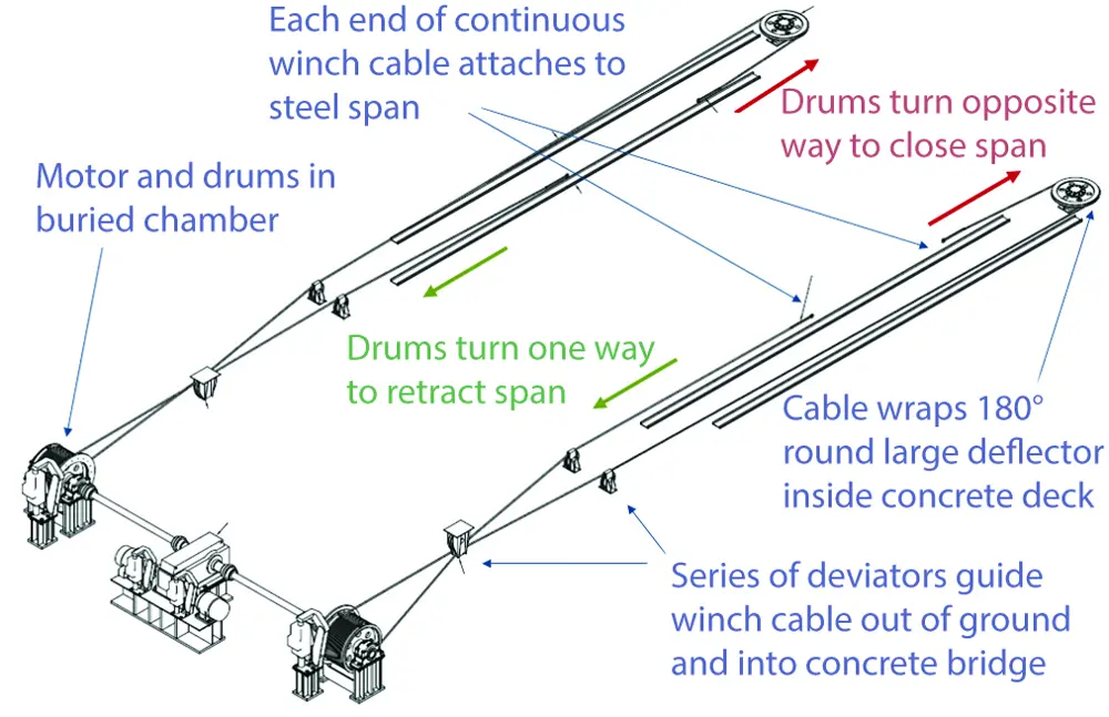
Each drum within the buried chambers has a winch rope wrapped around it, one end of which runs along the track on the side of the concrete spans and attaches to the rear of the steel span. The other end of the rope routes through the inside of the concrete box girder, turns 180 degrees around a large deflector sheave (a pulley with a grooved wheel) and returns to attach to the steel span a few metres forward of the rear attachment point. Depending on the direction in which the drums are turned by the electric motors, the steel spans are made to either open or close © Hardesty & Hanover
Design challenges
The sinusoidal plan curvature, with east and west sides on opposite curvatures of differing magnitudes, presented certain challenges in the design and construction. Aside from driving the bridges around these curves, which required each of the four winch drums to be slightly different diameters, the curvature complicated the shape of the fixed and moving spans.
As an aside, the curved alignment led to an unfortunate rumour that there was an error in the horizontal misalignment and that this was the reason for the delayed delivery of the steel spans. Standing on one concrete span and looking straight across the water to the other concrete span, before the steel spans came to site, it did indeed appear that the spans were transversely offset. However, when the steel spans were eventually delivered (delayed because of difficulties with the steel fabricators) the curvature became obvious, and the rumoured ‘misalignment’ disappeared. While adding complexity, the curvature helped the engineers achieve a slightly higher navigation clearance in the middle of the bridge by providing more length.
The steel spans are highly complex in their geometry – no two cross sections are the same – and they constantly change because of the varying structural depths in elevation and the curves on plan
The steel spans are highly complex in their geometry – no two cross sections are the same – and they constantly change because of the varying structural depths in elevation and the curves on plan. The moving steel girders have four inclined webs in the cross section: two inner webs and two outer webs. These are the elements that primarily resist shear and torsion (twisting) in the girder. The outer webs are formed from conical surfaces, which is easily done in steel plate, but the inner webs lie on warped surfaces that do not naturally provide good shear resistance. Therefore, the solution was to divide each inner web panel into two triangles by creasing on the diagonal and welding a tee stiffener along the inside of the crease. As these inner web elements were the closing panels of the steel box girders and internal access for welding was not possible in some places, the tee stiffeners had to stop short of the panel corners. The team had to revert to first principles and non-linear finite element modelling to prove that placing gusset plates to the ends of these stiffeners, at the relatively stiff corners of the panel, afforded them sufficient torsional restraint to ensure their stability and that of the overall web panel.
Another specific aspect that the design team had to deal with was a stringent requirement relating to pedestrian-induced vibrations. After the well-publicised problems experienced by London’s Millennium Bridge in 2000, when the structure swayed from side to side as hundreds of pedestrians walked across it, the dynamic behaviour of all footbridges has been in the spotlight. COWI (while still Flint & Neill) was closely involved in the investigations and solution development for the London Millennium Bridge and is an expert in this field. For the Inner Harbour Bridge, the client wanted to allow for large synchronous crowds dancing to music in phase with the bridge motion and this resulted in the need for a series of tuned mass dampers installed within the steel spans. These control movement amplitudes by responding to, and counteracting, the bridge’s motion.
For the Inner Harbour Bridge, the client wanted to allow for large synchronous crowds dancing to music in phase with the bridge motion and this resulted in the need for a series of tuned mass dampers installed within the steel spans
The project suffered several setbacks during construction including the rejection of sub-standard fabrication and the original contractor’s bankruptcy, which in turn led to considerable delays in delivery and the sourcing of a new contractor. Up until the end, concerns remained about achieving the desired quality of the finishes, and the smoothness of the geometry in the face of huge commercial and programme constraints. The designers spent a lot of time and energy trying to get the client and the new contractor to appreciate the importance of achieving the desired levels of quality.
User experience
Since its opening in July 2016, more than 10,000 cyclists and over 20,000 pedestrians use the bridge daily. It has dramatically reduced commuting times and improved key transit routes in the Danish capital.
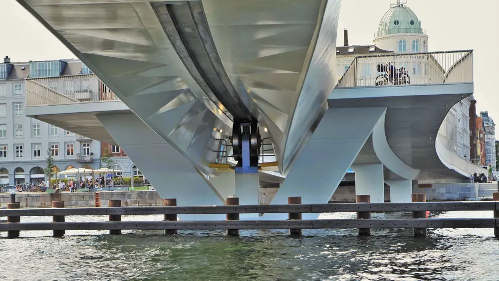
The underside of the bridge shows where the inner webs were divided into triangles. The gives an interesting crystalline appearance when viewed from the underside as the light reflects off the water. The fixed forward rollers and the transverse guide wheel are just visible. The guide wheel runs along a slot to control the extending position of the moving spans © Cezary Bednarski
The main disadvantage for bridge users on most opening bridges is the fact that they are kept well away from the action on the river, such as when a tall ship passes by. The design of the Inner Harbour Bridge provides an opportunity for the bridge user to experience the action close hand; people can stand on any one of four horizontal viewing platforms on the fixed concrete approach spans that reach towards the navigation channel, even when the bridge is operating, which enables them to be almost virtually within arm’s reach of passing vessels. Many people congregate on the bridge to enjoy the views of the harbour, as well as using it as a crossing.
The result is a bridge that is not only an important commuter route, but has also become a popular landmark in one of the most prominent parts of the city
The design and apparently simple, quiet and effortless operating mechanism disguises the complexity of the structural engineering challenge of creating the bridge. The result is a bridge that is not only an important commuter route, but has also become a popular landmark in one of the most prominent parts of the city.
***
This article has been adapted from "Copenhagen's 'kissing' bridge", which originally appeared in the print edition of Ingenia 73 (December 2017)
Contributors
Ian Firth FREng is a consultant at COWI and a Consulting Structural Engineer at Ian Firth Structural Engineering. At the time of publishing, he was Director of COWI. During his career, Ian has been involved with world-famous bridge projects including the strengthening of the Severn, Erskine and West Gate bridges, and the concept design of Stonecutters Bridge in Hong Kong. He has also been the designer of many smaller, award-winning bridges such as the Swansea Sail and Lockmeadow footbridges in the UK. Ian is an advocate of bridge-building charity, Bridges to Prosperity.
Amar Bahra is Associate Director at COWI UK LIMITED.. At the time of publishing, he was Principal Engineer. Besides the Inner Harbour Bridge, he has worked on many high-profile projects including West Gate Bridge in Melbourne, a retractable pitch at a North London football stadium, Wimbledon No. 1 Court, Royal National Theatre, London Olympic Stadium, and Messina Bridge between Sicily and mainland Italy.
Keep up-to-date with Ingenia for free
SubscribeRelated content
Civil & structural

Building the Shard
The Shard is one of London's most iconic buildings. The tallest in Western Europe, it was designed by Italian architect Renzo Piano and dominates the city’s skyline. Ingenia spoke to John Parker, project director for structural engineers WSP, who outlined the engineering decisions made in building the enormous steel and glass structure.

FlexiArch
Arch bridges are strong, durable and require little maintenance. However, very few had been built since the early 1900s until the FlexiArch was developed and launched in 2007. Now, there has been a minor renaissance for this ancient form of construction.

Creating user-friendly buildings
For Michelle McDowell, a former Business Woman of the Year, a passion for joined-up design thinking and building information modelling with a user-friendly approach has enabled her to pioneer revolutionary changes in her field.

Troja Bridge
In November 2014, one of the world’s largest network arch bridges was officially opened in Prague. The UK may soon have its first network arch bridge if the go-ahead is given for a new rail project in Manchester.
Other content from Ingenia
Quick read

- Environment & sustainability
- Opinion
A young engineer’s perspective on the good, the bad and the ugly of COP27

- Environment & sustainability
- Issue 95
How do we pay for net zero technologies?
Quick read

- Transport
- Mechanical
- How I got here
Electrifying trains and STEMAZING outreach

- Civil & structural
- Environment & sustainability
- Issue 95