Quieter, more efficient propellers
When Charles Parsons humiliated the pride of the Royal Navy at Queen Victoria’s Diamond Jubilee in 1897, it heralded a transformation in seafaring. His Turbinia, the first steam turbine-powered ship in the world, was the fastest vessel of its time, arriving unannounced at the Fleet Review in the Solent and weaving rings around the lumbering warships in full view of the dignitaries attending.
Yet while developing his revolutionary propulsion system, Parsons struggled to convert the power generated by his steam-driven turbine into forward momentum- something was sapping the energy from his propeller, preventing his experimental ship from achieving the speeds he had expected. For some reason, his vessel could only manage a speed of 19 knots when his calculations suggested it should be able to achieve a top speed of 40 knots.
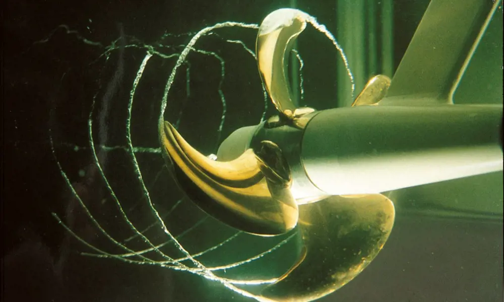
Sir Charles, as he later became, discovered the culprit was 'cavitation'. As a propeller rotates at high speed, it can cause the water behind it to essentially boil, creating bubbles, or cavities, to form in the water. This wastes energy rather than helping to drive the vessel forward.
Over time, [cavitation] can ruin propellers by eroding the metal and is responsible for a large amount of the noise and vibration experienced on modern ships
Nearly 140 years afterParsons discovered the problem, however, cavitation is still posing challenges for ship designers, passengers and crews. Over time, it can ruin propellers by eroding the metal and is responsible for a large amount of the noise and vibration experienced on modern ships - see Caviation explained.
Parsons attempted to overcome his problem by building one of the world's first cavitation tunnels. His modest equipment is still on display at the Discovery Museum in Newcastle alongside the Turbinia itself. That first cavitation tunnel, however, is dwarfed by modern facilities, that have sprung up around the world. Amoung the largest is the Large Caviation Channel in Memphis, Tennessee, where the US Navy tests its largest submarine and surface ship propulsion systems.
Rolls-Royce has one of the busiest cavitation tunnels in the world at its Hydrodynamics Research Centre in Kristinehamn, Sweden. Operating for more than 70 years, it has tested more than 1,500 different propellor designs and conducts around 40 new tests each year. The site has a traditional cavitation tunnel with a volume of 117m3, and a second, free-water surface containing almost 400m3 of water. Together, they have allowed Rolls-Royce to become one of the leading centres of research into propellor design and ways to reduce the cavitation that plagues them.
Caviation explained
🛳️ The violent noises produced from propeller blades that can resonate into the ship
Cavitation occurs as a result of changes in pressure in the water as the propeller blades rotate through it. Most people know that at normal atmospheric pressure, water will boil at 100°C. If the pressure drops, however, the temperature needed to turn water into steam also falls – which is why water boils at lower temperatures on top of mountains.
When a propeller spins rapidly through water, it creates high pressures on the front of the blade and a low pressure on the back. While it is this pressure difference that helps to generate the thrust from the propeller, if it gets too high, the water around the blade can vaporise, producing bubbles, cavities in the water close to the surface of the blades. However, as the bubbles leave the blades, the pressure around these cavities changes, causing them to implode violently and pop. This generates a crackling noise, much like someone is repeatedly throwing stones at the bottom of the hull. The cavitation helps generate pressure pulses towards the hull surface which can resonate far into the ship through metal plating, girders and the steel structure, and can disturb passengers in the restaurants or cabins above.
Vortexes produced by the tips of the blades – often the first type of cavitation to occur on a rotating propeller – also produce noise that radiates out into the water and back into the ship.
The noises produced also often span a wide band of frequencies – between 40 Hz and 100 Hz – meaning they can resonate within the structure of the ship itself, producing a cacophony of bashing sounds and ringing that can be unpleasant, and at times, troubling for those onboard.
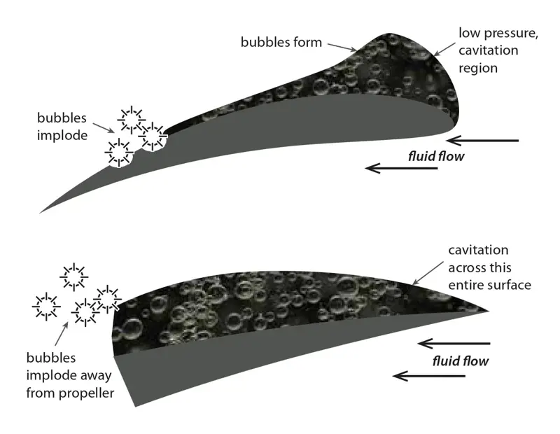
Difference between normal propeller section (top) which demonstrates the risk of cavitation erosion when the cavities implode towards the surface and a super cavitating section (bottom). The super-cavitating section prevents the risk of erosion by allowing the cavities to implode behind the propeller blade.
Blade design
By altering the pitch, camber and profile of the blades, engineers are able to alter the way bubbles that form on a propeller. Adding tiny winglets to the end of the propeller blades can also helped tackle tip vortex cavitation. The winglets work much like those that can be seen on the end of modern passenger jet wings. A propeller blade is, essentially, a rotating wing. Adding upturned fins to the end of these hydrofoil blades can help to equalise some of the pressure on both sides of the blade tip, reducing the risk of cavitation occurring.
This has led to some unconventional propeller designs, such as the curved tips of the Kappel propellers of MAN Diesel and Turbo, or the Contracted Loaded Tips of Spanish firm Sistemar, but tests have shown they can bring great improvements in efficiency.
The most radical design to be tried by Rolls-Royce has involved 90° winglets on the end of each blade, but such approaches need care as they can generate vortexes and cavities of their own. Ultimately the best way to deal with cavitation is to keep the loading of the propeller down. This means also increasing the efficiency of the propeller in the water to obtain as much thrust from its movement as possible.
Perhaps the best ways to achieve this are to make the propeller blades larger in size and to increase their number. The US Navy used this approach on its Ohio-class nuclear powered submarines, with a design that is still a closely guarded secret. The scant details that do exist in the public domain suggest it has seven thin, highly curved blades to help the vessel slip quietly and efficiently through the water.
engineers were able to optimise five- bladed, highly skewed propellers to meet the demanding noise and vibration requirements without harming the ship's efficiency
Rolls-Royce faced similar challenges of maintaining efficiency while reducing noise when working on a new cruise ship, Mein Schiff 3, but for very different reasons. Fitted with a 270 m2 room in the centre of the vessel, it is the first ship to be fitted with a fully equipped concert hall. With seating for 300 guests, it would not do to have the orchestra's performance drowned out by noises and shuddering through the ship from the stern.
To compound the issue, the designers of Mein Schiff 3 wanted to build a 167 m2, diamond-shaped glass façade spanning two decks at the stern of the ship within which are housed many of the ship's 11 restaurants and 12 bars. While solutions like floating vibration-damping floors can go some way to cut noise levels, they can only do so much.
Using physical models of the ship's propeller together with advanced computer modelling of various designs, engineers were able to optimise five- bladed, highly skewed propellers to meet the demanding noise and vibration requirements without harming the ship's efficiency. The five-blade design enabled the propellers to deliver 14 MW of power to create a top speed of 21 knots while keeping vibration and pressure fluctuations in the water to far lower levels than could be achieved with a four-bladed design. Skewing the blades also allows for a smoother flow of water from the hull over the length of the blades, helping to share the load and reduce the pressure pulses that can occur from disturbances caused by the movement of the ship through the water.
Propellor/Hull relation
However, in many cases, changing the design of the propeller is not enough. As the screw of a propeller usually sits at the rear of a ship, the water it encounters is rarely a smooth, steady flow. Instead it meets a turbulent, churning current thrown into a state of chaos by the passage of several tonnes of metal through the liquid ahead of it. Indeed, the wake left by the hull creates disturbances in the water that can alter the pressure around the propeller blades. This can also increase the risk of cavitation on the blades.
Traditionally, propellers were designed and built around the structure of the vessel, but they are now far more optimised for the ships they are to be fitted to than they were 10 to 15 years ago. Modern ships are increasingly designed using advanced computer modelling techniques that allow the hull and propeller to be created to complement each other.
By ensuring a steadier flow of water from the hull into the area where the propellers will be operating, and keeping the propeller the optimal distance from the hull, noise and vibration can be reduced while allowing the propeller to generate thrust as efficiently as possible. Placing a bulb on the rudder behind the propeller hub reduces the losses behind the propeller and improves the propulsive performance. Rolls-Royce has been experimenting with different bulb shapes to see how they influence the performance of the propeller.
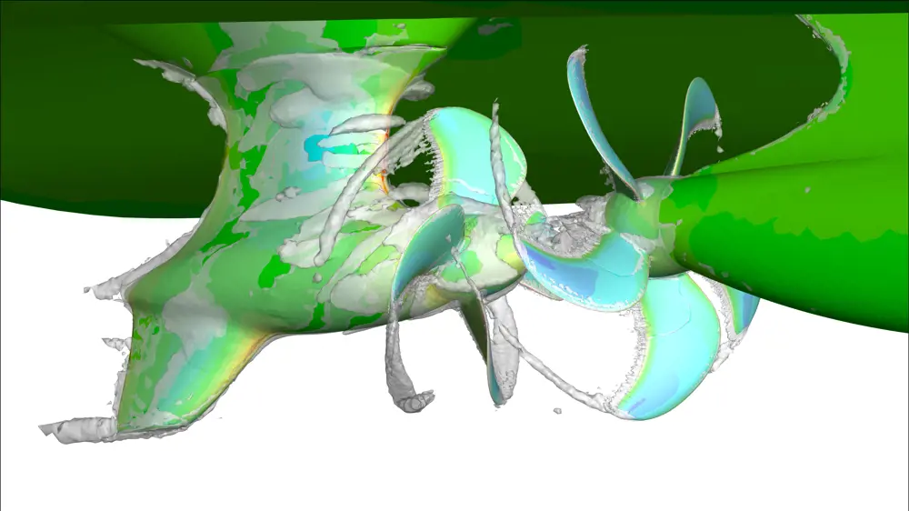
CFD simulation of a contra-rotating propulsion system for a mega-yacht. It sows an Azipull mechanical asimuthing thruster behind a five-bladed controllable pitch propellor © Rolls-Royce
Ultimately, however, it may only be possible to squeeze a small amount of extra efficiency – perhaps as little as one or two per cent – out of a propeller blade. By itself, this may not be enough to allow it to rotate at speeds below those when cavitation becomes a major problem.
Propellers are constrained by where they have to be on a vessel to provide forward thrust. They have to remain below the surface to prevent air from being drawn down, which can have an impact on the efficiency and increase noise. They cannot be too close to the hull in order to keep pressure pulses passing into the ship to a minimum and blade loading puts limits on their size.
But by playing with the way that the swirl spiralling off from the propeller interacts with another crucial element found at the stern of a ship – the rudder – it is possible to achieve further gains in efficiency. By designing the rudder so that it can regain as much of the energy in the water as possible, it is feasible to reduce the drag it creates and even generate additional thrust.
An asymmetric rudder can help to achieve this. The rudder profile can be bent in opposite directions in its lower and upper sections, and adapted to the rotation in the flow of water to reduce drag.
However, extra care needs to be taken to avoid cavitation occurring around the rudder which can quickly disintegrate under the eroding force generated by collapsing bubbles. Engineers are now beginning to explore the possibility of designing the rudder and propeller as one integrated unit. This can not only improve the ship’s thrust but also increase its manoeuvrability.
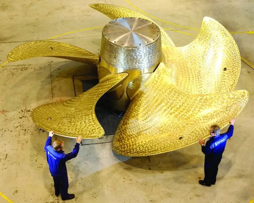
Inspection of one of the QE-class Aircraft carrier propellers prior to delivery from the factory in Kristinehamn, Sweden © Rolls-Royce
Avoiding detection
Greater speed, high manoeuvrability and as little noise in the water as possible are all particular demands of military vessels. Sound waves travel great distances through water and the distinctive sound of a propeller can make ships easy to pick out among the other noises of the ocean by predatory submarines lurking beneath the waves.
Propeller noise can often be so distinctive that sonar operators are able to not only identify a particular class of ship or submarine from its noise signature but also the individual vessel. Yet for the Royal Navy’s new Queen Elizabeth Class aircraft carriers, the twin propellers have to be able to shift 65,000 tonnes when a vessel is fully laden with up to 40 planes, helicopters and crew – three times the displacement of the UK’s current Invincible Class aircraft carriers. The new aircraft carriers’ engines will be capable of delivering nearly 40 MW of power to each propeller to give a top speed of 25 knots.
Although overall responsibility for the vessels lies with the Aircraft Carrier Alliance, Rolls-Royce was given responsibility for the hydrodynamic design of the propellers and the rudders. Each propeller had to be limited to a diameter of just 6.7 m owing to other aspects of the design and performance requirements. Each blade would be under extreme loading at full speed.
Propeller noise can often be so distinctive that sonar operators are able to not only identify a particular class of ship or submarine from its noise signature but also the individual vessel.
To cope with this, Rolls-Royce, along with the other partners on the project, opted for an innovative adjustable bolted propeller. It features five blades bolted from the inside around a hollow hub, which has slotted holes to allow the blade pitch angle to be adjusted during service.
This means the propellers can be adjusted to match the RPM of the engines. Each propeller shape is optimised to a different shaft speed, while the adjustability will also allow the Royal Navy to compensate for increases in displacement that may occur during the vessel’s lifetime.
The individual blades can also be replaced if they become damaged. With each propeller weighing around 33 tonnes each, this modular design makes it far easier to repair than having to replace an entire propeller.
The design has also allowed the propellers to deliver around 50,000 horsepower each – making them the highest powered propellers ever produced by Rolls-Royce. The company has also been contracted to design the vessels’ twin rudders, optimising the initial semi-spade design so that they can work in cooperation with the propellers. The hull of each ship will also feature an enormous bulbous bow to help ensure a smoother flow of water towards the stern.
Future trends
With the aid of advanced computer simulation and design, ships in the future are likely to benefit from this integrated approach to propulsion design to an even greater degree. New systems such as permanent magnet motors, which form a rim to turn the propeller shaft from the periphery instead of the centre, promise to bring further improvements in efficiency and noise reduction.
The Royal Netherlands Navy, among others, has begun investigating the potential of new materials for propeller blades. Most modern ship propellers are made from a nickel aluminium bronze, which is tough enough to withstand the erosion that can occur during use. However, using composite materials, such as carbon fibre and resins, could lead to new types of flexible propeller blades which remain rigid until pressure on the blades reaches a point when they will deflect, helping to reduce cavitation. They could also be used to soak up pressure differences coming the water flow off the hull.
Dutch design firm Airborne Composites, for example, built a prototype composite propeller for the Royal Netherlands Navy’s minesweeper vessels using carbon, glass and epoxy resin. Tests showed that while it was tough enough to resist damage and the stresses of use, the blades also flexed under load, producing a hydroelastic effect that reduced cavitation.
While Rolls-Royce has yet to explore this technique itself, it could mark the future of propeller design.
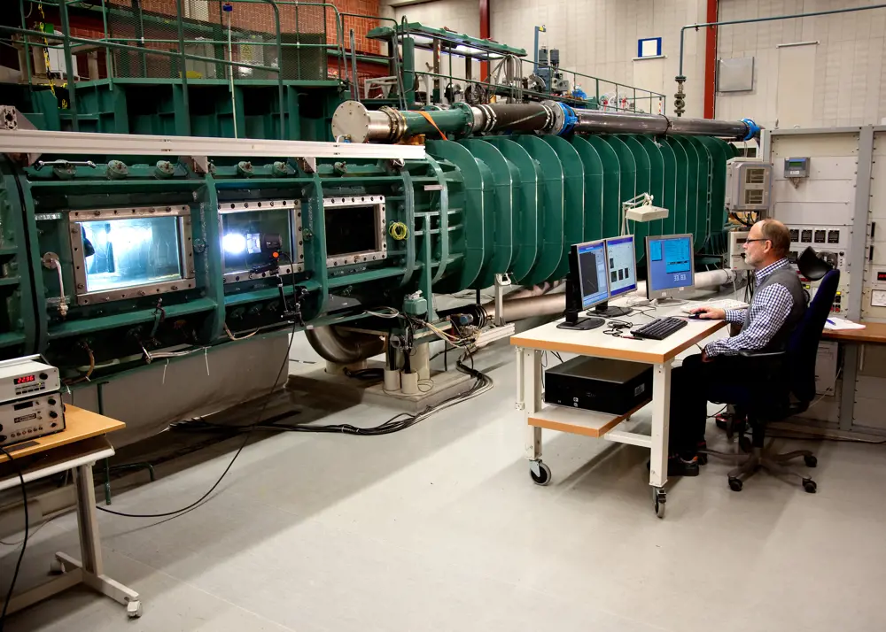
Established in 1971, the Rolls-Royce Hydrodynamic Research Centre in Kristinehamn, Sweden designs and manufactures a range of propulsion systems. These include fixed and controllable pitch propellers, water jets and pods used across a wide range of vessels in the offshore, merchant and naval sectors. It houses two large cavitation tunnels which are used to test a wide range of propeller and impeller designs © Rolls Royce
There are also new types of propulsion systems that are being used to overcome the problems of cavitation and the unwanted noise it generates. The US Navy’s latest Virginia-class attack submarines use pump-jet propulsion, originally developed by BAE Systems for the Royal Navy’s older Swiftsure-class submarines. Newer Rolls-Royce pump jet propulsors are now being used on the Royal Navy’s new Astute-class nuclear powered submarines. These use rotor blades within a duct that draw water in through an intake and push it out of a nozzle at the back, producing quieter thrust with lower risks of cavitation at higher speeds.
However, there are some who believe the future of ship design may actually lead marine engineers to create vessels that produce large amounts of cavitation. By getting a ship to travel fast enough that it starts to produce supercavitation – where so many bubbles are produced around a vessel it essentially becomes encased – it is possible to reduce the drag on it considerably. Air lubrication systems (air bubbles produced by compressors to reduce frictional drag of the hull) are increasingly being used in some new ships.
Russia has already used supercavitation in the design of their VA-111 Shkval torpedoes which can reach speeds of up to 200 knots, while New Hampshire-based Juliet Marine Systems have built a prototype high-speed vessel that utilises the phenomenon. Meanwhile, researchers at China’s Harbin Institute of Technology have announced that they have found a way of reducing the speed at which supercavitation begins by showering the hull of the vessel with liquid to create a ‘membrane’ around it.
By getting a ship to travel fast enough that it starts to produce supercavitation – where so many bubbles are produced around a vessel it essentially becomes encased – it is possible to reduce the drag on it considerably
While this may not lead to the quietest of rides, it suggests there may yet be a way the humble propeller and the bane of Charles Parsons’ Turbina – cavitation – can exist together side by side.
***
This article has been adapted from "Quieter, more efficient propellers", which originally appeared in the print edition of Ingenia 65 (December 2016).
Contributors
Richard Gray
Author
Göran Grunditz MSc NavArch joined the Rolls-Royce Hydrodynamic Research Centre in Sweden in 2000, on graduating in Naval Architecture from the Royal Institute of Technology in Stockholm. At the centre, he has been working with fixed and controllable pitch propellers, cavitation testing, and hydrodynamic development/research. He became the manager of the centre in 2010. He currently works as the manager of the Hydrodynamic organisation at Kongsberg Maritime, Propulsion & Engines incl. Kongsberg Hydrodynamic Research Centre (KHRC).
Keep up-to-date with Ingenia for free
SubscribeRelated content
Maritime & naval

Modelling ships in danger
Stricken ships in danger of breaking up, sinking, capsizing or losing their fuel or cargo need expert help to be rescued. Lloyd’s Register’s Ship Emergency Response Service (SERS) was set up to provide this support.
Building Britain's biggest warships
The 1998 Strategic Defence Review called for the UK Armed Forces to be able to operate with more agility to confront situations on a worldwide basis and resulted in the requirement for two new Queen Elizabeth Class aircraft carriers, HMS Queen Elizabeth and HMS Prince of Wales, one of the UK's largest engineering projects.
Against the tide
The Royal National Lifeboat Institution introduced the Shannon class all-weather lifeboat in 2014, which uses cutting-edge technology, is faster and more manoeuvrable than existing vessels, and has a quicker and safer launch and recovery system. Read about the design and production of the lifeboat.
How to create the perfect wave
From small waves lapping at your feet and swells suitable for surfing to storm waves for testing structures and even tsunamis, waves of any shape and any size can now be engineered. What are the techniques and conditions needed to model waves and what makes some more powerful than others?
Other content from Ingenia
Quick read

- Environment & sustainability
- Opinion
A young engineer’s perspective on the good, the bad and the ugly of COP27

- Environment & sustainability
- Issue 95
How do we pay for net zero technologies?
Quick read

- Transport
- Mechanical
- How I got here
Electrifying trains and STEMAZING outreach

- Civil & structural
- Environment & sustainability
- Issue 95