Future-proofing the next generation of wind turbine blades
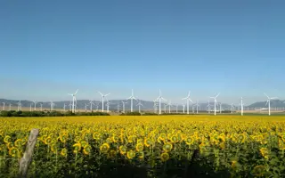
The current generation of offshore wind farms being deployed around the world are bigger and more efficient than ever before. The first offshore wind farm, Vindeby, was installed in Denmark in 1991 and comprised turbines of 450 kW (kilowatts) with blades 16 metres long. Since then, turbines have advanced considerably, with machines now that are 8 MW (megawatts) and over. Manufacturers are increasingly designing larger, more effective models that are contributing to cost reductions in offshore wind. As a result, bigger turbines need longer blades, with current manufacturers designing and testing blades up to 88 metres long. However, such an increase in scale carries associated physical and environmental engineering challenges that the industry must address.
Longer blades present engineering challenges around blade design, materials and condition monitoring. Wind farm owners and operators need to design longer blades that can survive in the harsh offshore environment, and at the same time improve their understanding of issues such as behaviour in real-world conditions, erosion and remedial repair requirements as the assets age.
As the UK’s flagship technology innovation and research centre for wind, wave and tidal energy, the Offshore Renewable Energy (ORE) Catapult is helping to tackle these challenges
As the UK’s flagship technology innovation and research centre for wind, wave and tidal energy, the Offshore Renewable Energy (ORE) Catapult is helping to tackle these challenges through a combination of engineering expertise, industry collaborations, and its test and demonstration facilities.
The benefits of blade testing
🔧 How ORE Catapult’s facilities reduce costs of unplanned maintenance and increase availability and output
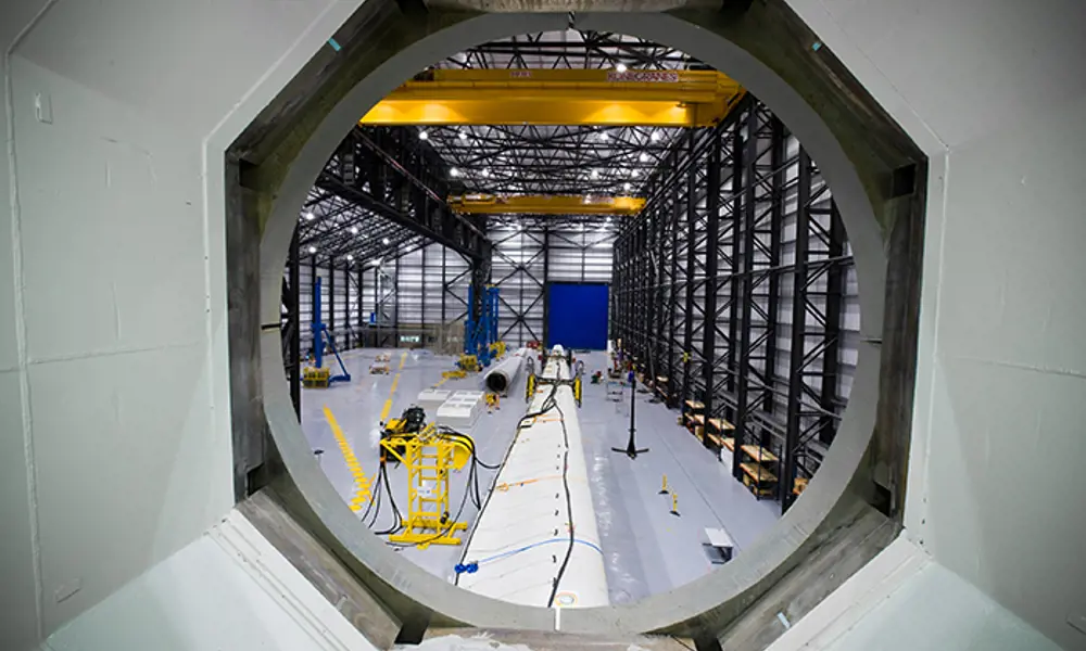
ORE Catapult’s 50 metre and 100 metre facilities are used to carry out industry blade tests, and its 7 MW (megawatt) Levenmouth demonstration turbine is used for blade research and development. This approach to industrial research and development, and the employment of representative testing, can bring many benefits to equipment manufacturers, asset owners and investors. This helps to reduce the cost of unplanned maintenance and increases availability and output. Design margins can be reduced, saving costs on materials and contributing to more efficient designs. The iterative design process is accelerated, which can reduce the time and cost of getting a new technology to market.
Challenges for longer blades
As blades get longer, the most severe structural load cases change during rotation meaning that the fundamentals of blade design also have to change. For example, self-weight from gravity loading and the torsional stiffness of the blade become more significant. However, by minimising the increase in weight as the blade gets longer, the change in stresses is reduced. Two factors are key in reducing the weight of longer blades: more efficient composite design, which can be achieved by using materials with high strength-to-weight ratio; and the development of better manufacturing methods, resulting in reduced defects in the blade, and therefore increased strength.
In terms of blade materials research, offshore environmental conditions are very poorly characterised. No databases exist of detailed temperature, humidity, ultraviolet (UV) and rain droplet size distributions data in the offshore environment for rotating equipment. Instead, data is transferred from that collected by oil and gas platforms. The effect of this missing data is that current accelerated coating, weathering and rain erosion tests may not be appropriate and may explain, in part, the difference in the performance of blade coatings during accelerated testing, compared with actual performance in real-world conditions.
The erosion of the leading part of the turbine blade – the part that experiences the strongest impact of rain droplets and other airborne particulates – is a problem
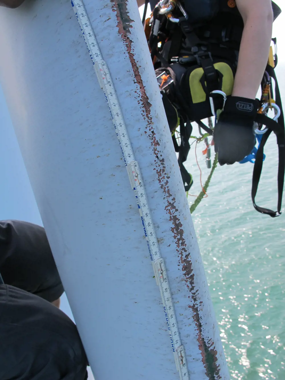
Blade leading-edge erosion is one of the key challenges facing the offshore wind industry. Leading-edge erosion is accelerated offshore because of harsher environmental conditions and can prove costly for offshore wind farm owners and operators, through lost power generation and revenue
The phenomenon of blade leading-edge erosion is a significant one for the offshore wind industry. The erosion of the leading part of the turbine blade – the part that experiences the strongest impact of rain droplets and other airborne particulates – is a problem both on- and offshore, but the erosion seems to be accelerated offshore because of the harsher environmental conditions. Erosion affects the aerodynamic performance of the blade by reducing the amount of lift the blade generates and increasing its drag. It also affects structural integrity as water entry and UV (ultraviolet) light exposure can lead to structural damage. This can result in reduced turbine efficiency, reliability and availability, and increased operations and maintenance (O&M) activity, with repairs in situ being difficult and expensive. All of this proves costly for offshore wind farm owners and operators, through lost power generation and revenue.
Blade leading-edge erosion is one of the key challenges facing the offshore wind industry. Leading-edge erosion is accelerated offshore because of harsher environmental conditions and can prove costly for offshore wind farm owners and operators, through lost power generation and revenue
New coatings are now coming to market that have significantly improved performance in accelerated rain erosion testing. However, good performance in accelerated testing has not always translated into good in-service performance, because of a lack of understanding of the many factors that affect blade erosion. These factors include the test method itself and a lack of understanding about the erosion damage mechanisms connected to material properties. This can be caused by a lack of analysis techniques that can cope with the very high-strain, high-frequency environment, a lack of understanding of offshore conditions, and insufficient research into the interactions between the blade structure and the coating layers, and how they are affected by, for example, the application process and blade manufacturing.
The biggest issue surrounding blade repair is environmental conditions: UV radiation, temperature and humidity can affect the resins and fabrics used during the process and potentially reduce the quality of the repair
ORE Catapult’s blade leading-edge erosion programme aims to better quantify the magnitude of leading-edge erosion across the sector by investigating its effect on wind turbine blade efficiency, assessing the impact on aerodynamic performance and structural integrity and on the overall cost of electricity generated from offshore wind. One programme objective is to minimise O&M activities while maximising reliability and availability, thereby cutting the cost of electricity generated from offshore wind.
Once blade damage occurs, repairs are generally carried out in situ: by crane access onshore and by rope access offshore. The biggest issue surrounding blade repair is environmental conditions: UV radiation, temperature and humidity can affect the resins and fabrics used during the process and potentially reduce the quality of the repair. New repair materials with wider application conditions are required, as well as new curing techniques to apply heat in situ during rope access. For blade leading-edge repairs due to erosion, the quality of the repair affects the performance of the repair leading-edge coating.
ACT blade
🌬️ Developing the next- generation of engineered textile wind turbine blades
ORE Catapult is working with Edinburgh-based SME ACT blade to develop and test next-generation engineered textile wind turbine blades.
After responding to one of ORE Catapult’s innovation challenges, the team worked with engineers from yachting design specialists SMAR Azure, which resulted in the spin-off company ACT Blade. The aim was to study the feasibility of adapting the sail modelling technology into modular blades that are over 50% lighter than those in use today.
Put simply, a lighter blade can achieve greater power production. If a blade is lighter, it can be made longer than the current 55 metre standard. In turn, the longer blade captures more wind and increases energy production, which lowers the levelised cost of energy (LCoE).
Made up of an internal composite structure and high-tech textiles, as opposed to the prevailing fibreglass, ACT Blade’s design has the potential to reduce the levelised cost of offshore wind by 8.7% while increasing energy production by 9.7%.
The development of modular blades also has implications for developing countries, where poorer infrastructure means full-length blades are all but impossible to transport. There are environmental advantages, too: while glass-fibre blades are landfilled at the end of their working life, ACT Blades will use recycled carbon fibre.
After helping ACT Blade to secure several rounds of investment, ORE Catapult is developing a new test rig at its facility in Blyth to validate and demonstrate a section of the blade.
Blade testing
Before blades are deployed in the field, manufacturers use blade test facilities to prove, validate and de-risk their new technologies to improve investor and customer confidence. This can be a long and expensive process, and is not always representative of how blades operate in real-world conditions. The number of test halls capable of carrying out very long blade tests is also limited.
In preparation for testing, wind industry-specific simulation software is used to determine the loading that wind turbine blades can expect to experience in real-world conditions. This software takes into account how the turbine structure moves when mechanical loading is applied to it. Loads arise from the wind, waves, tides, and the wind turbine control and electrical systems.
Thousands of scenarios (or ‘load cases’) are simulated and wind turbine design standards dictate the conditions that the turbine will see in each load case. Once these simulations have been performed, the extreme values of the loads at a series of points along the length of the blade are determined. Safety factors are applied to these loads to account for the fact that the turbine may see greater loads in service than in the simulations. These extreme values form an ‘envelope’, and are described by a maximum and minimum value in each direction.
wind industry-specific simulation software is used to determine the loading that wind turbine blades can expect to experience in real-world conditions
The everyday loading that the wind turbine will see is also simulated. These simulations might include, for example, the turbine operating at different wind speeds, the turbine starting up and shutting down, and the turbine in a parked condition when the wind is either too light or too strong for it to operate. These load cases form a subset called ‘fatigue’ load cases, and are analysed in a different way to the extreme loads.
A fatigue analysis takes into account how the strength of the materials used in the blade will decrease over time because of repeated loading. Imagine bending a paper clip: it will not break the first time you bend it, but if you continue to bend it back and forth then eventually it will snap. The goal of a fatigue analysis is to ensure that although the blade will go through perhaps 100 million loading cycles during its lifecycle, it will still have plenty of life left after 25 years of operation.
Wideblue
📷 Detecting blade deformation with sophisticated optical technology
Optical condition monitoring takes place inside a wind turbine blade, using the digital image correlation system developed by ORE Catapult and Wideblue
ORE Catapult is working with Wideblue – formerly Polaroid’s R&D lab – to develop its optical technology into a sophisticated digital image correlation system that can detect blade deformation.
The Blade Optical Health Monitoring (BOHEM) project will develop a low-cost, optimised, optical condition monitoring solution for blades that can be used during the development of new designs and in the operational field.
During the first phase of the 12-month project, Wideblue’s sensing technology will be applied to ORE Catapult’s research blade to learn more about its capabilities. It will then be deployed on the 7 MW Levenmouth demonstration turbine, where it will undergo trials in a real-world, operational offshore environment. The data generated will be used to monitor individual blade health, allow early detection of any changes in performance, instruct more effective maintenance and allow for better justification of life extensions.
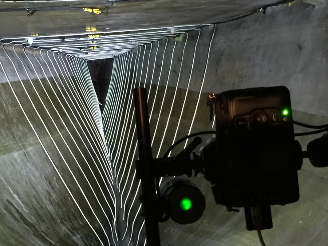
Optical condition monitoring takes place inside a wind turbine blade, using the digital image correlation system developed by ORE Catapult and Wideblue
Static and fatigue testing
Wind turbine blades are type tested, meaning that each new design, or any substantial alteration to an existing design, is validated. Full-scale blade tests are performed by bolting the blade to an extremely strong, fixed concrete hub so that they are cantilevered out horizontally. Loads are then applied to the blade to ensure that it can survive the loading that was calculated at the design stage.
Outputs from the blade fatigue simulation software, developed by ORE Catapult in partnership with Durham University, and certified by DNV GL. The software certification provides vital assurance that the results that the new test method generates will conform to industry standards and guidelines
Wind turbine blades have two main sources of loading: aerodynamic loading from the wind, and gravity loading caused by their own weight as the blades spin. The aerodynamic loading acts mainly in the ‘flapwise’ direction. If you think of a blade as being like an aeroplane wing, then the flapwise load would act to move the blade up and down. The gravity loads act mainly in the edgewise direction; in the plane wing analogy, they act to move the blade forwards and backwards. Blade tests are primarily designed to ensure that the blade can survive loading in these two directions.
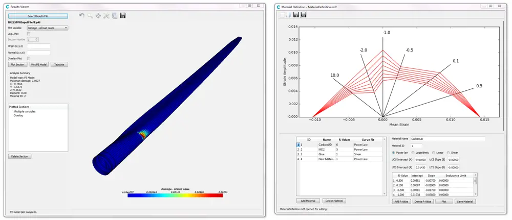
Outputs from the blade fatigue simulation software, developed by ORE Catapult in partnership with Durham University, and certified by DNV GL. The software certification provides vital assurance that the results that the new test method generates will conform to industry standards and guidelines
In a static test, the blade is loaded using between five and eight winches at a series of points along the blade. The winches are attached to the blade by wooden clamps that fit snugly around the aerodynamic profile of the blade, and loads are applied to the blade in four directions: flapwise maximum and minimum, and edgewise maximum and minimum. The winches stay in the same place for these four tests and the blade is rotated about its long axis. The loading is calculated in such a way that the blade undergoes more extreme loading in each direction at each point than was calculated in the simulations.
After the static tests, the blade is fatigue tested. This test involves exciting the blade at its natural frequency so that it undergoes several million cycles. The loads are calculated so that the blade is subjected to an equivalent amount of damage as it will experience during its service life.
Bi-axial testing
ORE Catapult is addressing the challenge of reducing the time and costs of blade testing, and making it more representative of real-world operating conditions, by developing a bi-axial testing method. This joint industry and academic collaborative approach to designing the bi-axial testing methodology aims to reduce fatigue test times by almost a half, and overall test times by up to 25%.
However, testing bi-axially is not as simple as applying the single axis test loads at the same time. This would produce an extremely conservative test that would damage the blade much more than its service life. This is because, in service, the flapwise loads are mainly aerodynamic and the edgewise loads are mainly driven by gravity. The aerodynamic loading varies as the rotor spins, with a maximum load reached when the blade is at the top of its cycle (because the wind tends to blow faster higher up, a phenomenon called wind shear) and a minimum when the blade is at the bottom of its cycle (when it passes through stagnant air in front of the turbine tower). This means that the gravity loading lags behind the aerodynamic loading by 90°, which tends to drive the tip of the blade in a curve.
During a bi-axial test, in which both axes are excited simultaneously at their resonant frequencies, the blade will regularly experience combinations of loads that would not occur in practice because the flapwise and edgewise frequencies are very unlikely to be exactly the same – the tip of the blade will be driven in what is called a Lissajous curve.
The software enables the user to reduce material safety factors by a factor of two – this could potentially have significant implications for the amount of material required to produce the blade
ORE Catapult has addressed this problem by moving away from the conventional method of fatigue testing (which involves calculating test loads and then counting the number of cycles that the blade undergoes) in favour of monitoring how the theoretical damage is accumulating during the test. This means that the test loads do not need to be rigidly held at a given level, which is impossible when testing bi-axially because the flapwise and edgewise modes interact, and also allows the combination of fatigue tests to be optimised to match the damage that the blade is predicted to undergo in service.
The test method is dependent on knowing the theoretical fatigue damage that the blade would experience in service. For this reason, ORE Catapult has developed sophisticated wind turbine blade-specific fatigue analysis software that has been certified by DNV GL, a technical assessment, advisory, and risk management body. An accurate fatigue analysis has very tangible benefits, as it allows a substantial reduction in material strength safety factors. Compared to the more simplistic analysis, the software enables the user to reduce material safety factors by a factor of two – this could potentially have significant implications for the amount of material required to produce the blade.
Once a fatigue analysis has been performed to assess the service life damage, the result is fed into an optimisation routine. This aims to tune the flapwise and edgewise mode shapes (by altering the position and mass of the test equipment on the blade) so that the test loads cause damage that matches the service life damage over as much of the blade as possible.
With the test design complete, the blade test can begin. Strain gauge data from the blade test is processed into a format that can be read by the fatigue analysis software. This makes it possible to compare the damage subjected during the test to the predicted service life damage, which can then be presented to a certification body to demonstrate that the blade has been thoroughly tested.
After the fatigue tests, the static tests are repeated. This demonstrates that the blade can still survive the extreme loads, even if they occur at the end of the turbine’s lifetime.
The development of a bi-axial method of testing has attracted interest from industry, including a collaboration with international blade manufacturer LM Wind Power. The collaboration aims to reduce the cost of offshore wind by designing, validating and deploying the world’s largest offshore wind turbine blade. At 88 metres long, the blade will undergo bi-axial testing and – it is hoped – will achieve a significant reduction in the levelised cost of energy by means of lighter construction and a more predictable operational expenditure through reliability-driven design. ORE Catapult will test the blade in its 100 metre facility, alongside the continuation of its work on the issue of blade leading-edge erosion.
The development of a bi-axial method of testing has attracted interest from industry, including a collaboration with international blade manufacturer LM Wind Power
The 7 MW Levenmouth demonstration turbine provides training and development of skills vital for the future of the offshore wind industry. Researchers can develop a deeper understanding of a wide range of technologies as well as the operations and maintenance aspects of offshore wind turbines, with the ultimate goal of reducing the cost of energy.
***
This article has been adapted from "Futureproofing the next generation of wind turbine blades", which originally appeared in the print edition of Ingenia 70 (March 2017).
Contributors
Kirsten Dyer is ORE Catapult’s Senior Research Materials Engineer and is responsible for developing products, services and solutions in the area of materials on blades for the wind and tidal sectors. She previously worked for Gamesa and BAE Systems.
Peter Greaves is a Principle Research Structural Engineer (Blades) for ORE Catapult. He graduated in 2006 from Newcastle University with a degree in mechanical engineering and then studied for an MSc in renewable energy. ORE Catapult funded Peter’s doctoral studies on bi-axial blade fatigue testing.
Keep up-to-date with Ingenia for free
SubscribeRelated content
Design & manufacturing

Super cool(er)
Welsh startup Sure Chill has developed a cooler that uses the properties of water to keep its contents cool for around 10 days without electricity. This is ideal for storing items such as vaccines where electricity sources are unreliable.

R&D investment makes good business sense
In just five years, Dr Ralf Speth FREng has presided over a revolution in design and manufacturing that has helped create a new family of engines and has overhauled Jaguar Land Rover (JLR) production facilities.

Steel can arise from the ashes of coal
Thousands of people were laid off in the UK steel industry in 2015 and there are pessimistic future forecasts. Professor Sridhar Seetharaman of the Warwick Manufacturing Group argues that smaller, flexible steel mills implementing new technology would better cope with fluctuating global trends.

Integrating metrology in business and academe
Professor Jane Jiang’s interest in measuring began when she worked on a bus production line in China. She found that the best way to improve quality, consistency and productivity was through metrology, the science of measurement. Today, she runs the UK’s largest metrology research group.
Other content from Ingenia
Quick read

- Environment & sustainability
- Opinion
A young engineer’s perspective on the good, the bad and the ugly of COP27
- Environment & sustainability
- Issue 95
How do we pay for net zero technologies?
Quick read
- Transport
- Mechanical
- How I got here
Electrifying trains and STEMAZING outreach

- Civil & structural
- Environment & sustainability
- Issue 95